Composite phase change heat exchanger with medium and low pressure

A low-pressure evaporator and phase change heat exchanger technology, applied in indirect heat exchangers, heat exchange equipment, lighting and heating equipment, etc., can solve the problems of reducing exhaust gas temperature, condensation corrosion, ash blocking, etc. Effect of condensation and utilization of waste heat from flue gas

Inactive Publication Date: 2009-04-01
杨本洛 +1
View PDF0 Cites 38 Cited by
  • Summary
  • Abstract
  • Description
  • Claims
  • Application Information

AI Technical Summary

Problems solved by technology

Due to the SO in the boiler flue gas 3 Existence of the flue gas outlet temperature of the heating surface at the tail of the air preheater is limited, and the exhaust gas temperature is too low will cause the wall temperature of the heating surface to be lower than the acid dew point of the flue gas, resulting in serious condensation corrosion and ash blocking. Difficulties that must be faced by utilizing waste heat and reducing exhaust gas temperature
[0003] The composite phase change heat exchanger can recycle waste heat while maintaining a high minimum wall temperature, greatly reduce the exhaust gas temperature, and control the exhaust gas temperature to only about 15°C higher than the minimum wall temperature, which can usually control the wall temperature At 100 °C, the exhaust gas temperature is about 115 °C, but in practical applications, the thermal balance must also be dealt with in order to achieve the effect of avoiding condensation and reducing the exhaust gas temperature

Method used


Image

  • Composite phase change heat exchanger with medium and low pressure

Examples


Embodiment Construction

[0010] Further description will be made below in conjunction with embodiments of the present invention and accompanying drawings.

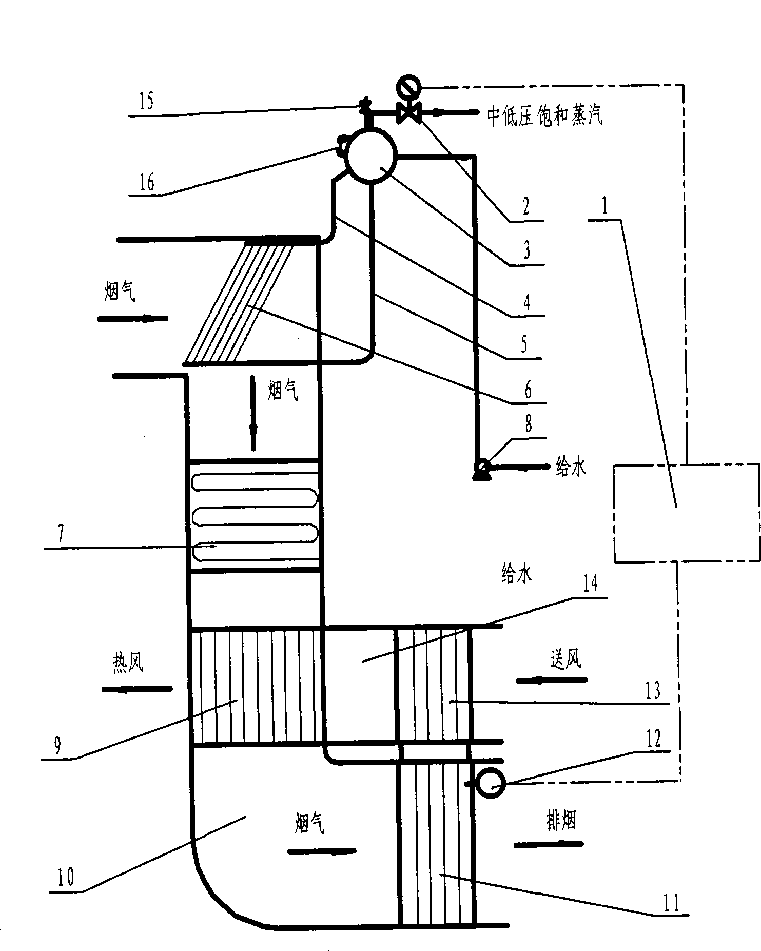
[0011] See the composite phase change heat exchanger with medium and low pressure evaporator shown in the accompanying drawing, including medium and low pressure evaporator 6 and steam drum 3, steam drum 3 is equipped with steam drum safety valve 15 and steam drum liquid level gauge 16 as usual. The medium and low pressure evaporator 6 communicates with the steam drum 3 through the ascending pipe 4 and the descending pipe 5. The steam drum 3 is provided with a water supply pipe connected to the water pump 8 and a steam output pipe connected to the heat user. Heat exchangers 13, 11. The low-pressure evaporator 6 is located above the economizer 7 in the flue 10, the upper section 13 of the composite phase change heat exchanger is placed in the original air duct 14 of the air preheater 9, and the lower section 11 is placed in the rear flue of the air...


PUM


Abstract

The invention discloses a composite phase change heat exchanger with a medium-pressure and low-pressure evaporator, which comprises the medium-pressure and low-pressure evaporator and a steam header which are communicated by an ascending pipe and a descending pipe, a water feeding pipe and a steam outputting pipe are arranged on the steam header, an upper section of the composite phase change heat exchanger is positioned in a wind channel of an original air preheater, and a lower section of the composite phase change heat exchanger is positioned in a back flue channel of the air preheater; an automatic control device of the composite phase change heat exchanger adjusts and controls the heat exchange volume of the evaporator and the wall temperature of the lower section of the composite phase change heat exchanger. The composite phase change heat exchanger not only directly produces low-pressure or medium-pressure steam by using the recycled heat through a steam generating device and provides heat usage as a heat supply, but also controls the thermal equilibrium among the heat exchange volumes of the flue gas, the medium-pressure and low-pressure evaporator, a coal economizer and the wall of the air preheater by adjusting the steam flow of the steam outputting pipe of the steam header through the automatic control device, and consequently leads the flue gas temperature at the outlet to be higher than a flue gas acid dew point on the lower section wall surface of the composite phase change heat exchanger, avoids moisture condensation and achieves the purpose of utilizing waste heat of the flue gas to the utmost degree.

Description

[technical field] [0001] The invention relates to a device for recovering and utilizing waste heat of boiler flue gas, in particular to a composite phase change heat exchanger with a medium and low pressure evaporator combined with an economizer and an air preheater in a flue. [Background technique] [0002] There are usually economizers and air preheaters in the exhaust flue of power plant boilers, which absorb part of the waste heat of the flue gas, but the exhaust gas temperature is usually 140°C to 160°C or higher, and there is still waste heat that can be used. Due to the SO in the boiler flue gas 3 Existence of the flue gas outlet temperature of the heating surface at the tail of the air preheater is limited, and the exhaust gas temperature is too low will cause the wall temperature of the heating surface to be lower than the acid dew point of the flue gas, resulting in serious condensation corrosion and ash blocking. It is a difficult problem to use waste heat and re...

Claims


Application Information

Patent Timeline
Patent Type & Authority Applications(China)
IPC IPC(8): F28D15/00F28F27/00
Inventor 杨本洛
Owner 杨本洛
Why Eureka
Try Eureka