Photonic forbidden band ceramic Sierpinski split antenna used for RFID system

A radio frequency identification system, photonic bandgap technology, applied in the direction of antenna, radiating element structure, electrical components, etc., to achieve the effect of small size, low cost and simple manufacturing process

Inactive Publication Date: 2012-10-10
XIAMEN UNIV
View PDF0 Cites 0 Cited by
  • Summary
  • Abstract
  • Description
  • Claims
  • Application Information

AI Technical Summary

Problems solved by technology

At present, there is no report on the related technology that combines Sierpinski fractal antenna, ceramic substrate material, and rectangular hole array photonic bandgap structure and applies it to the RFID system in the 2.4-2.4835GHz working frequency band.

Method used


Image

  • Photonic forbidden band ceramic Sierpinski split antenna used for RFID system
  • Photonic forbidden band ceramic Sierpinski split antenna used for RFID system
  • Photonic forbidden band ceramic Sierpinski split antenna used for RFID system

Examples


Embodiment Construction

[0024] The present invention will be further described below in conjunction with embodiment and accompanying drawing.

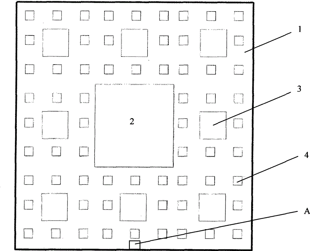
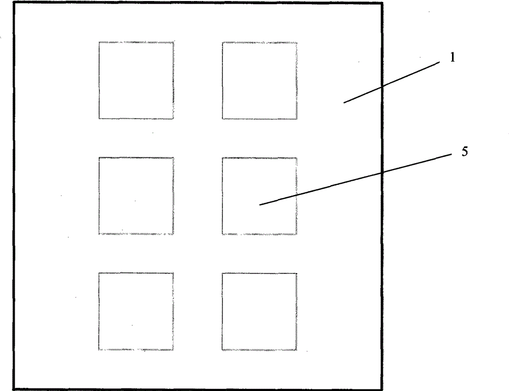
[0025] seefigure 1 and 2 , the present invention is provided with double-sided silver-plated ceramic substrate 1, both sides of ceramic substrate 1 are all provided with silver-plated layer, and one side silver-plated layer of ceramic substrate 1 is Sierpinski (Sierpinski) fractal antenna radiation patch (such as figure 1 As shown, it is a third-order fractal patch structure), and the silver-plated layer on the other side of the ceramic substrate 1 is an antenna ground layer, and a rectangular hole array photonic bandgap structure is etched on the antenna ground layer (such as figure 2 As shown, it is composed of 6 square holes 5 in 3 rows and 2 columns).

[0026] The relative permittivity of the ceramic substrate 1 is 26. The ceramic substrate 1 is a rectangular substrate with dimensions of 30mm±1mm in length, 30mm±1mm in width and 3.0mm±0.05mm in thickne...


PUM


Abstract

A photonic band gap ceramic Sierpinski fractal antenna used in a radio frequency identification system relates to a microstrip antenna, in particular to a photonic band gap ceramic Sierpinski fractal antenna used in a radio frequency identification system. The invention provides a photonic band gap ceramic Sierpinski fractal antenna which is used in a radio frequency identification system and is characterized by small size, wide bandwidth, low return loss and omnidirectional radiation property. The antenna is provided with a ceramic substrate, both two sides of the ceramic substrate are provided with a silver coating respectively, wherein, the silver coating on one side is a Sierpinski fractal antenna radiation patch, and the silver coating on the other side is an antenna ground plane, the antenna ground plane is provided with a rectangular hole array photonic band gap structure, and antenna feed points are arranged on the Sierpinski fractal antenna radiation patch.

Description

technical field [0001] The invention relates to a microstrip antenna, in particular to a photonic bandgap ceramic Sierpinski fractal antenna for a radio frequency identification system. Background technique [0002] RFID is the abbreviation of Radio Frequency Identification in English. Radio frequency identification technology is a non-contact automatic identification technology realized by radio frequency communication that emerged in the 1990s. RFID tags have the characteristics of small size, large capacity, long life, and reusability. They can support fast reading and writing, non-visual identification, mobile identification, multi-target identification, positioning and long-term tracking management. Combined with other technologies, it can be used in logistics, manufacturing, public information services and other industries to achieve efficient management and operation and reduce costs. With the continuous improvement and maturity of security soft information-related ...

Claims


Application Information

Patent Timeline
Patent Type & Authority Patents(China)
IPC IPC(8): H01Q1/38H01Q13/08
Inventor 游佰强林斌周建华熊兆贤郑建森徐伟明
Owner XIAMEN UNIV
Why Eureka
Try Eureka