
Casting parts method and forging press for forging casting part with side opening or pleural furrow, and adjustable wrench

An adjustable wrench and casting technology, applied in the field of adjustable wrench, can solve the problems of reducing manpower and material resources, shortening production cycle, low manufacturing cost, etc., and achieving the effect of reducing production cost, saving manpower and material resources, and reducing clamping torque

Inactive Publication Date: 2009-04-08
鲁宏
View PDF0 Cites 0 Cited by
  • Summary
  • Abstract
  • Description
  • Claims
  • Application Information

AI Technical Summary

Problems solved by technology

[0005] The purpose of the present invention overcomes the defects of the existing parts forming method with side holes or side grooves, which have many procedures, high cost and long cycle, and introduces forging into the forming process of this type of parts. The method has fewer procedures and reduces The required manpower and material resources are reduced, the manufacturing cost is low, and the production cycle is shortened; the internal structure of the parts made by the process method of the present invention is dense, the density is high, the toughness and mechanical strength are good, the deformation coefficient is small, and the surface finish is smooth. High and accurate in size; when processing adjustable wrench by this method, the cross-sectional shape of the sliding groove of existing adjustable wrench can be improved, so that the force of the adjustable wrench is reasonable, and the shaking gap between the movable jaw and the fixed jaw can be eliminated , prevent the shaking of the movable jaw when the wrench is pulled, improve the clamping accuracy, will not cause the reduction of the clamping torque, and prevent the deformation of the fixed jaw, prolong the service life of the movable wrench, and the manufacturing cost is low

Method used


Image

  • Casting parts method and forging press for forging casting part with side opening or pleural furrow, and adjustable wrench
  • Casting parts method and forging press for forging casting part with side opening or pleural furrow, and adjustable wrench
  • Casting parts method and forging press for forging casting part with side opening or pleural furrow, and adjustable wrench

Examples


Embodiment 1

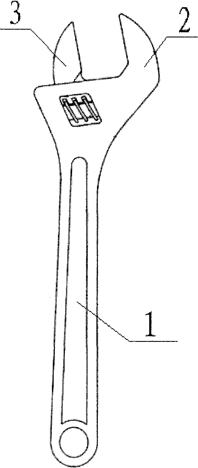
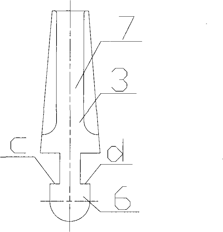
[0034] Such as figure 1 and figure 2As shown, the movable wrench includes a wrench body 1, a fixed jaw 2 and a movable jaw 3, the front end of the wrench body 1 is provided with a fixed jaw 2, and the fixed jaw 2 is provided with a sliding groove 4 and a sliding groove adjacent thereto. The rail 5 and the moving column 6 integrated with it are axially arranged below the movable jaw 3, and the moving column 6 is embedded in the sliding groove 4 and the sliding rail 5. The inner surfaces a and b of the slide groove 4 adjacent to the slide rail 5 are horizontal, and the corresponding outer surfaces c and d of the moving column 6 are also horizontal. When the wrench is working, the force acting on the inner surface of the sliding groove 4 is the force perpendicular to the a surface and the b surface, that is, the vertical force. This force has no component force in the horizontal direction, so the fixed jaw 2 and the movable jaw 3 can be eliminated. The gap between the adjustab...

Embodiment 2

[0046] This embodiment is the second production method of adjustable wrench, which adopts large-tonnage cold pressing, and mainly includes the following steps:

[0047] First, casting molding: the wrench body is initially formed by sand casting. Precision casting can also be used during casting, but it will increase production costs, and ordinary sand casting has already met the production requirements;

[0048] The second step is to detect the hardness of the wrench casting, and when the Rockwell hardness is less than HRC20, the casting is subjected to large-tonnage cold pressing;

[0049] The third step, forging: Put the wrench casting into the forging die, apply a small pressure on the wrench casting through the forging press, insert the side mold in the sliding groove of the wrench casting, the shape and size of the side mold must be consistent with the sliding groove The cross-sectional shape and size of the wrench are consistent, and then the wrench casting in the forgin...

Embodiment 3

[0053] Such as Figure 9 and Figure 10 There are three holes in the oil circuit connection cap of the automobile engine shown, wherein hole 15 and hole 16 are through holes, hole 14 is a blind hole, and the axis direction of hole 15 and hole 16 is perpendicular to hole 14, the oil circuit connection The processing method of the cap is as follows:

[0054] The first step, casting molding: the oil passage connecting cap is preliminarily formed by sand casting;

[0055] The second step, heating: reheat the casting of the cast oil connection cap to its plastic deformation temperature. The specific temperature value is determined according to the material of the oil connection cap;

[0056] The third step, precision forging: using such as Figure 8 In the forging press shown, put the heated oil passage connecting cap casting into the forging die. When putting it in, make the axial direction of the hole 15 and the hole 16 parallel to the axial direction of the forging press, and...


PUM


Abstract

The invention relates to a method for forging a casting with a side hole or a side groove and a forging press used in the method and provides a monkey wrench machined by the method. The invention overcomes the drawbacks that the prior method for forming parts with side holes or side grooves has a plurality of procedures, high cost and long period, and introduces forging into a process for forming parts with a side hole or a side groove. The method has less working procedures, reduces labor and materials, has low manufacture cost, and shortens the production period. Parts formed by the method have high density, high toughness and mechanical strength, small coefficient of deformation, high surface finish quality and accurate size. In addition, the money wrench machined by the method has a reasonable load bearing structure, eliminates a shake gap between a movable jaw and a fixed jaw to prevent the movable jaw shakes during the operation of the wrench, improves the accuracy of clamping, prevents reduction in clamping torque force and deformation of the fixed jaw, prolongs the service and achieves low manufacture cost.

Description

technical field [0001] The invention relates to a casting and forging method, in particular to a casting forging method with side holes or side grooves, a forging press used in the method and an adjustable wrench formed according to the method. Background technique [0002] At present, commonly used parts with side holes or side grooves, such as adjustable wrenches, pipe wrench, etc., are usually produced by machining methods, that is, complex production processes such as drilling, milling, and slots are required. It usually requires the simultaneous cooperation of multiple workers and multiple machines to process and form, which has high production costs and long production cycles. With the development of casting technology, casting processing is more and more used in the manufacture of such parts. As we all know, the inside of the casting is easy to produce pores, and the surface is prone to cracks. At the same time, the internal structure of the casting is loose. Therefo...

Claims


Application Information

Patent Timeline
IPC IPC(8): B21J5/02B21J13/02B21J1/06B25B13/12B25B23/00B21J9/06
Inventor 鲁宏
Owner 鲁宏
Learn More