Master-slave mode direct current carrier communication system and its control flow

A communication system, DC carrier technology, applied in the field of communication, can solve problems such as no longer applicable, increase the complexity of the slave power supply system, increase the host load, etc., to avoid the impact of data transmission speed, improve reliability and integration , the effect of eliminating the requirement for polarity connection

Active Publication Date: 2009-04-08
南通炜天电子科技有限公司
View PDF4 Cites 44 Cited by
  • Summary
  • Abstract
  • Description
  • Claims
  • Application Information

AI Technical Summary

Problems solved by technology

[0005] 1. Each node slave needs to have a special module to send and receive data, and the cost is high
[0006] 2. AC carrier greatly increases the complexity of the slave power system
[0007] 3. The performance of each module used by the node slave is very different, and modules such as isolation transformers are difficult to integrate
[0009] 1. The data receiving circuit is composed of resistor divider or Zener tube rectification, which leads to a large power consumption of the slave and increases the load of the host
[0010] 2. The communication interface is placed behind the rectifier bridge, which is no longer applicable to systems that use bipolar data high-speed transmission
[0011] In the slave communication interface provided by the patent ZL200420084237.4, a dedicated module is used to receive and send data, but the integration is poor, and it cannot meet the application requirements of small slaves.

Method used


Image

  • Master-slave mode direct current carrier communication system and its control flow
  • Master-slave mode direct current carrier communication system and its control flow
  • Master-slave mode direct current carrier communication system and its control flow

Examples


Embodiment approach

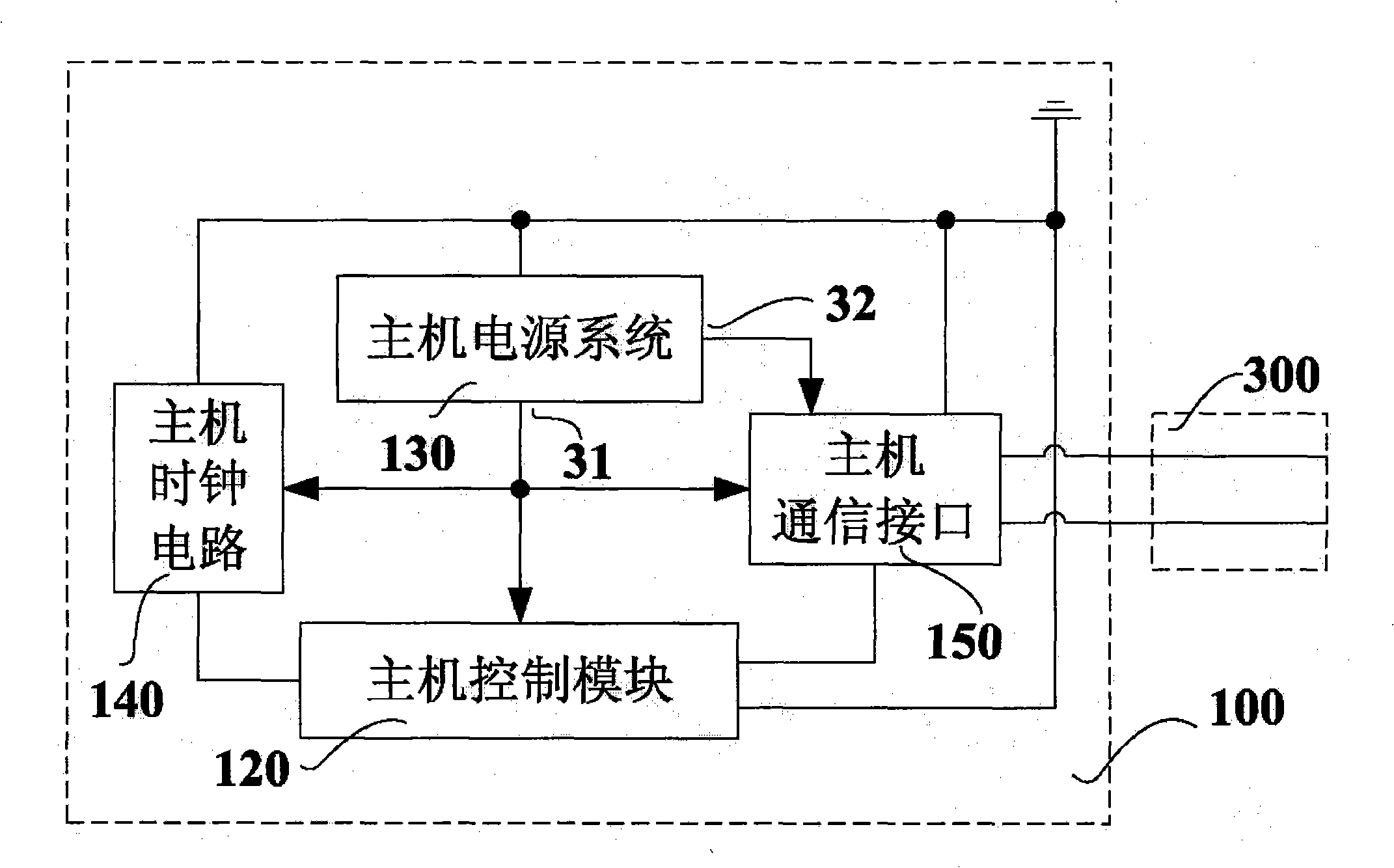
[0113] 1. If Figure 4 , the unipolar data modulation module 101 and the unipolar data demodulation module 102 are commonly connected to the working voltage output terminal 31 of the host power system 130 , and are powered by the host power system 130 . One end of the unipolar data modulation module 101 and the unipolar data demodulation module 102 is respectively connected to the host control module 120 for data interaction with the host control module 120 . Each of the unipolar data modulation module 101 and the unipolar data demodulation module 102 also has one end grounded, that is, connected to the ground wire. The communication voltage input terminal 10 of the unipolar data modulation module 101 is connected to the communication voltage output terminal 32 of the host power system 130 . The modulated signal output terminal 11 of the unipolar data modulation module 101 leads to the outside of the unipolar communication interface 110 via the unipolar data demodulation modul...


PUM


Abstract

The invention provides a master-slave mode DC carrier communication system; wherein, a master machine comprises the clock circuit of the master machine, the power system of the master machine, the communication interface of the master machine and the control module of the master machine; a slave machine comprises the communication interface of the slave machine, a rectifier bridge circuit, an energy storage module, the power system of the slave machine, the clock circuit of the slave machine and the control module of the slave machine. The master machine can be the initiation device of an electronic detonator; the slave machine can be the electronic detonator. A unipolarity communication interface consisting of a unipolarity data modulating module and a unipolarity data demodulating module or a bipolar communication interface consisting of a bipolar date modulating module and a bipolar data demodulating module can be selected as the communication interface of the master machine; the communication interface of the slave machine can comprise the data modulating module and the data demodulating module of the slave machine. The invention also provides a control method for the master machine and the slave machine in the system. The technical scheme realizes the bidirectional data alternation between the master machine and the slave machine when the master machine supplies a working power to the slave machine, thereby improving the maintainability of the system.

Description

technical field [0001] The invention relates to the communication field, in particular to a master-slave direct current carrier communication system and its control flow. Background technique [0002] In the centralized-distributed control system in the field of industrial control, industrial field control buses such as PROFIBUS, LONWOKS, CAN, and FF are often used. Its characteristic is that each distributed node needs to have a power supply system independent of the bus, and the polarity of the bus must be connected accurately in order to perform data exchange normally. [0003] In the carrier communication system, the power line carrier communication system is often used at present, that is, the host loads the data information to be transmitted on the base frequency power line in the form of high frequency waves, so as to realize the power supply to the slaves of each node and complete the data at the same time. transmission. The characteristic of this system is that th...

Claims


Application Information

Patent Timeline
Patent Type & Authority Applications(China)
IPC IPC(8): H04B3/54G05B19/418
CPCY02P90/02
Inventor 颜景龙刘星李风国赖华平张宪玉
Owner 南通炜天电子科技有限公司
Why Eureka
Try Eureka