
Fire-proof test device of concrete multi-span continues beam or plate

A test device, concrete technology, applied in the direction of measuring device, machine/structural component testing, material inspection product, etc., can solve the problem of inability to measure fire resistance

Inactive Publication Date: 2009-04-15
HARBIN INST OF TECH
View PDF0 Cites 11 Cited by
  • Summary
  • Abstract
  • Description
  • Claims
  • Application Information

AI Technical Summary

Problems solved by technology

[0003] The purpose of the present invention is to solve the problem of using a combustion furnace to measure the fire resistance of existing building components. It is only a simple measurement of the fire resistance limit of building components, but it cannot be used to measure the fire resistance of building components such as internal force changes and deformation rules under fire. Determining the problem of providing a fire resistance test device for concrete multi-span continuous beams or slabs

Method used


Image

  • Fire-proof test device of concrete multi-span continues beam or plate
  • Fire-proof test device of concrete multi-span continues beam or plate
  • Fire-proof test device of concrete multi-span continues beam or plate

Examples


specific Embodiment approach 1

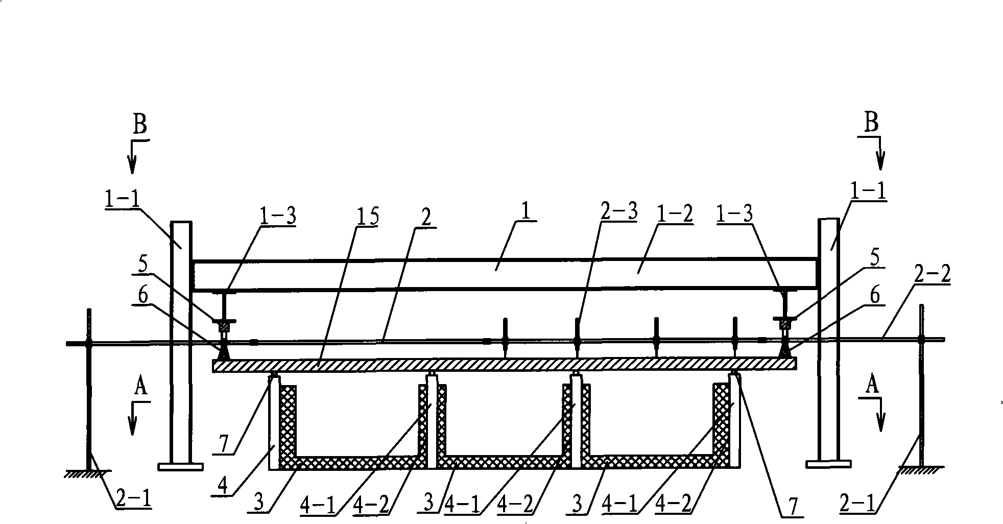
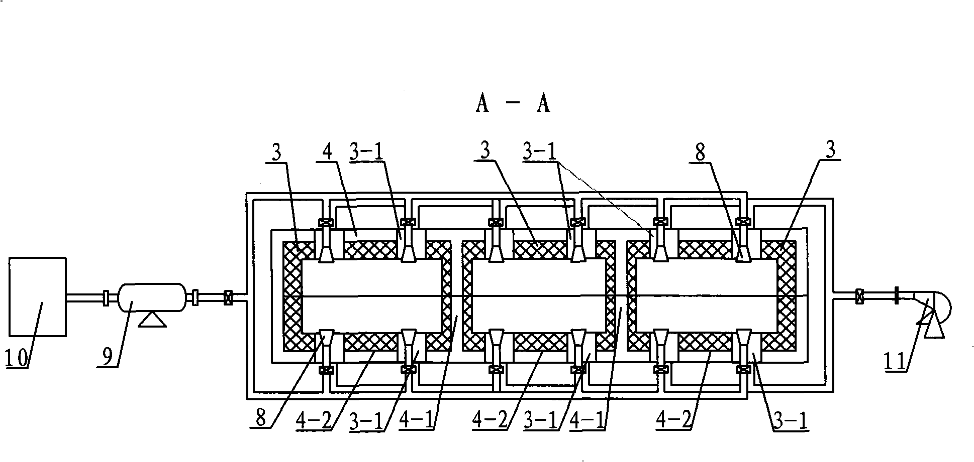
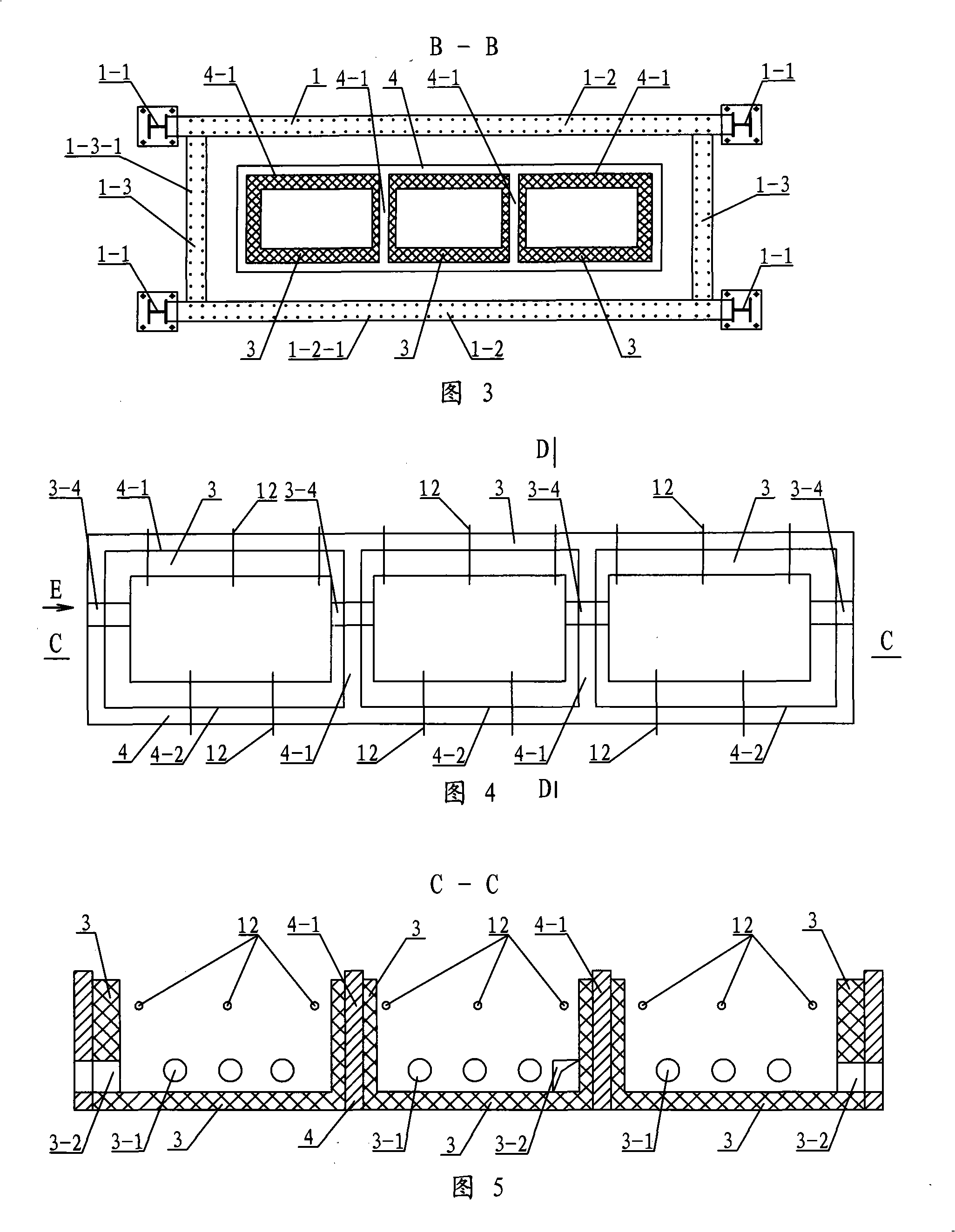
[0007] Specific implementation mode one: combine Figure 1 to Figure 6 and Fig. 8 illustrate this embodiment, this embodiment comprises reaction force frame 1, and reaction force frame 1 is made up of four columns 1-1, two reaction force longitudinal beams 1-2 and at least one reaction force beam 1-3, The two ends of each reaction force longitudinal beam 1-2 are respectively connected with the side end surfaces of two upright columns 1-1 by high-strength bolts, and the reaction force beam 1-3 is located between the two reaction force longitudinal beams 1-2, and the reaction force The position of the beam 1-3 can be adjusted along the reaction beam 1-2 according to the position of the applied load or reaction constraint required by the test, and the two ends of the reaction beam 1-3 respectively pass through the two reaction beams 1-2 High-strength bolt fastening, it also includes at least one displacement measuring device 2, at least two-span furnace body 3, specimen support 4...

specific Embodiment approach 2

[0008] Specific implementation mode two: combination figure 1 , Figure 5 and Image 6 The present embodiment will be described. In this embodiment, the upper plane of the furnace body 3 is lower than the upper plane of the specimen holder 4 . This design can ensure that the specimen has enough deformation space.

specific Embodiment approach 3

[0009] Specific embodiment three: this embodiment is described in conjunction with Fig. 9, the furnace body wall around the furnace body 3 of the present embodiment is formed by refractory bricks, and the furnace body wall around the furnace body 3 is formed by ordinary red bricks. The furnace body 3 is filled with refractory fibers between the inner wall and the outer wall around the furnace body 3, and the bottom of the furnace body 3 is made of two layers of refractory bricks. This design makes the furnace body 3 have a good thermal insulation effect, simple structure and low cost.


PUM


Abstract

The invention discloses a concrete multi-span continuous beam or plate fire-resistant experiment device, and relates to a fire-resistant experiment device, aiming at solving the problems that the present measurement of building unit fire-resistance is only the measurement of fire resistance duration of building units and the present measurement can not survey and evaluate the fire-resistant performance such as internal force changes, deformation rules and the like of the building units in fire. Upright posts are placed on the surrounding of the support saddle of test pieces; two roof bolts are placed on the ground of the two longitudinal outer sides of a reaction force frame; a weighing sensor is arranged under a reaction force beam; a jack is arranged under the weighing sensor; a nozzle is arranged at the place of a jet; an oil pump is connected with the nozzle and is also connected with a fuel tank; a blower is communicated with the jet; a flue is arranged at the lower parts of a furnace body and the side wall of the adjacent testing piece support saddle thereof; and the upper parts of the furnace body and the side wall of the adjacent testing piece support saddle are provided with at least two thermoelectric couples. The invention provides test devices for the concrete multi-span continuous beam or plate fire-resistant experiments, satisfies the experimenting requirements such as warming, boundary constraining, reaction force measuring, loading, etc.

Description

technical field [0001] The invention relates to a fire resistance test device. Background technique [0002] With the progress of society, the continuous increase of population and the increasing density of buildings, fires occur more and more frequently, causing huge losses to the property of the country and the safety of people's lives. Especially in recent years, the urban population density is increasing day by day, and the rapid development of high-rise buildings has increased the frequency of fire occurrence and the difficulty of fire fighting. In order to avoid unnecessary losses and strengthen the fireproof and fire-resistant performance of buildings, we should first understand the stress behavior and deformation rules of building structural beams or slabs under fire, and measure the fire-resistant performance of beams or slabs. The fire resistance test of components only uses the combustion furnace to simply measure the fire resistance limit of building components,...

Claims


Application Information

Patent Timeline
IPC IPC(8): G01N33/38G01B21/32G01M19/00G01M99/00
Inventor 董毓利杨志年吕俊利张大山王勇
Owner HARBIN INST OF TECH
Learn More