Minitype optical DC/AC electric field sensor
An electric field sensor and optical sensing technology, applied in the field of optoelectronics, can solve the problems of the lack of effective methods for direct measurement of DC high voltage and the difficulty of realizing the modulation of the DC voltage to be measured, etc., and achieve high bandwidth, reliable measurement, long-term and stable measurement effect
- Summary
- Abstract
- Description
- Claims
- Application Information
AI Technical Summary
Problems solved by technology
Method used
Image
Examples
no. 1 example
[0117] Such as figure 2 As shown, the beam emitted by the broadband light source 28 passes through the polarizer 25, first passes through a depolarizer 24, and then is polarized and split and modulated when passing through the optical phase modulator 40, and the output two independent orthogonal linearly polarized mode beams The fast and slow polarization axis orientations of a polarization-maintaining optical fiber 37 are respectively transmitted to the electro-optic crystal.
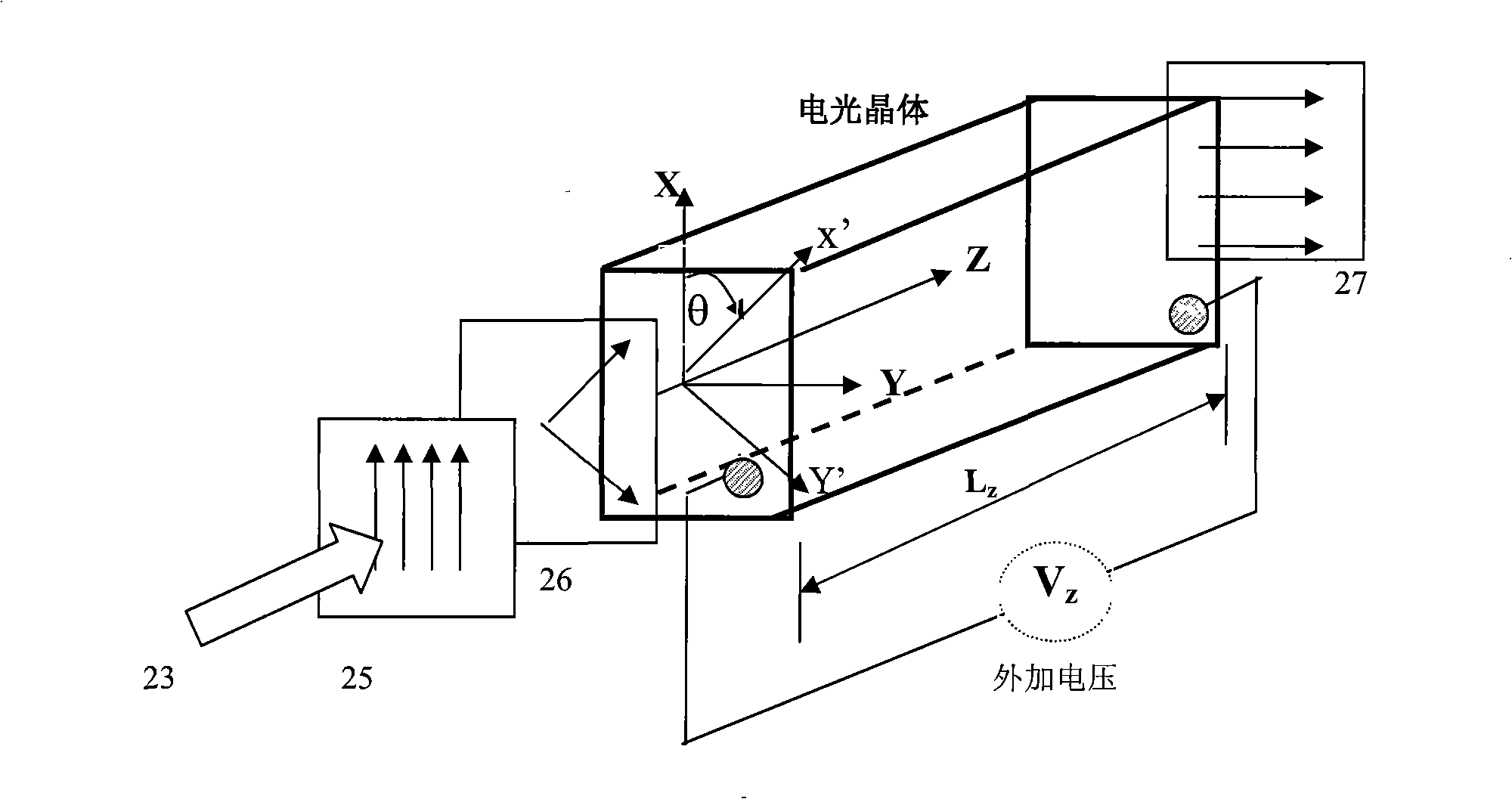
[0118] The two orthogonal linear polarization directions of the incident linear polarization transmitted by the polarization-maintaining light 37 to the crystal are aligned parallel to the crystal intrinsic polarization axis (x', y') (that is, at 45 degrees to the crystal axis), and the corresponding refraction The rates are:
[0119] n±Δn (8)
[0120] Among them, n: the refractive index of the electro-optic crystal when there is no external electric field;
[0121] Δn: Due to the linear electro-op...
no. 2 example
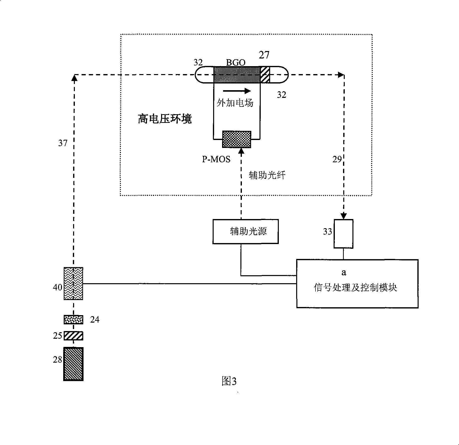
[0162] As shown in Figure 3, after the light beam emitted by the broadband light source 28 passes through the polarizer 25, it first passes through a depolarizer 24, and then is polarized, split, and modulated when passing through the optical phase modulator 40, and the output two independent orthogonal The linearly polarized mode beams are respectively transmitted to the electro-optic crystal in the directions of the fast and slow polarization axes of the same polarization-maintaining fiber 37 .
[0163] The two orthogonal linear polarization directions of the incident linear polarization transmitted to the electro-optic crystal by the polarization-maintaining optical fiber 37 are aligned parallel to the crystal intrinsic polarization axis (x′, y′; that is, 45 degrees to the crystal axis respectively), and the corresponding The refractive indices are:
[0164] n±Δn (21)
[0165] Among them, n: the refractive index of the electro-optic crystal when there is no external electr...
no. 3 example
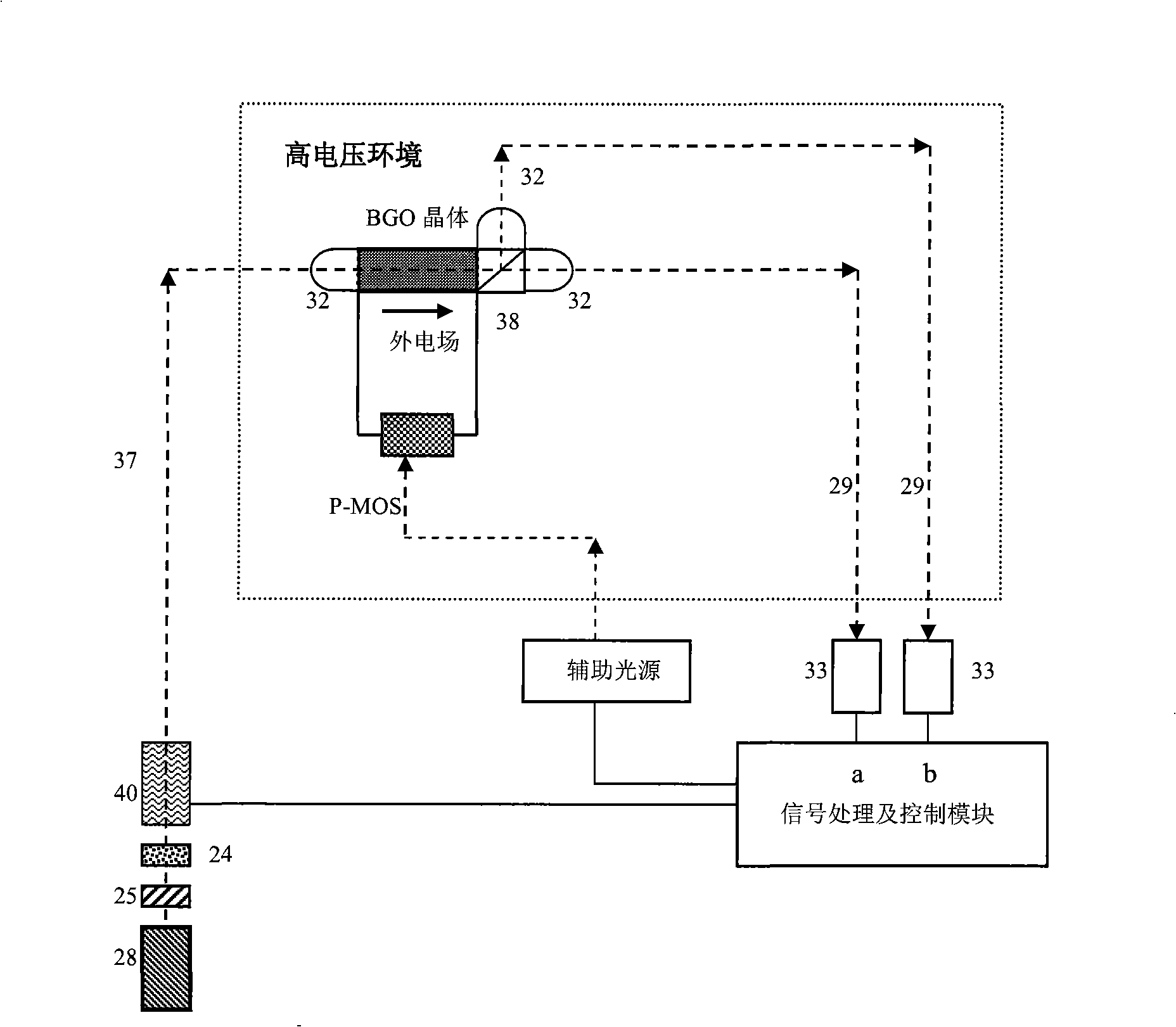
[0238] Such as Figure 4 As shown, the light beam emitted by the broadband light source 28 passes through the polarizer 25, passes through the depolarizer 24, and then is polarized, split, and modulated when passing through the optical phase modulator 40 to give two independent parallel polarization modes, which are composed of two The root polarization-maintaining fiber 37 each transmits a polarization mode to the polarization combiner 38, and the two independent orthogonal polarization modes formed are input in directions parallel to the intrinsic polarization axis of the electro-optic crystal.
[0239] The signal generator gives a pulse rectangular voltage signal which is applied to the optical phase modulator 40 to form a square wave π / 2 phase delay dynamic bias between two independent orthogonal polarization modes.
[0240] An analyzer 27 is placed at the beam output end of the crystal, and its optical axis is at 45 degrees to the intrinsic polarization axes of the two cr...
PUM
 Abstract
Description
Claims
Application Information
 - R&D
- Intellectual Property
- Life Sciences
- Materials
- Tech Scout
- Unparalleled Data Quality
- Higher Quality Content
- 60% Fewer Hallucinations
Browse by: Latest US Patents, China's latest patents, Technical Efficacy Thesaurus, Application Domain, Technology Topic, Popular Technical Reports.
© 2025 PatSnap. All rights reserved.Legal|Privacy policy|Modern Slavery Act Transparency Statement|Sitemap|About US| Contact US: help@patsnap.com


