Microstrip linear filter, duplexer and radio-frequency device

A technology of microstrip line filter and radio frequency device, which is applied in the field of communication, and can solve the problems of large loss, reduction of effective conduction cross-sectional area of ​​microstrip conductor, and high cost

Inactive Publication Date: 2009-04-29
HUAWEI TECH CO LTD
View PDF0 Cites 22 Cited by
  • Summary
  • Abstract
  • Description
  • Claims
  • Application Information

AI Technical Summary

Problems solved by technology

so figure 2 In the duplexer, if the general PCB board is used, the overall loss is relatively large; if low loss is to be achieved, for example, in some high-frequency applications, it is necessary to use a high-grade RF board with a low loss tangent ( Such as RO3003 and other boards), but the price of this board is generally high and the cost is high; moreover, the material of high-grade radio frequency boards is generally soft, if the assembly is not done properly, the deformation of the PCB board will easily lead to changes in the indicators;
[0011] In addition, due to the influence of the high-frequency skin effect of the conductor
The effective conduction cross-sectional area of ​​the microstrip conductor is reduced, resulting in an increase in high-frequency loss, which is also the largest part of the microstrip loss

Method used


Image

  • Microstrip linear filter, duplexer and radio-frequency device
  • Microstrip linear filter, duplexer and radio-frequency device
  • Microstrip linear filter, duplexer and radio-frequency device

Examples


Embodiment Construction

[0027] The present invention will be described in detail below with preferred embodiments in conjunction with the accompanying drawings.

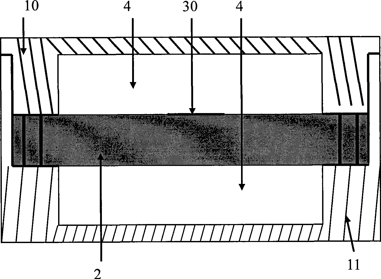
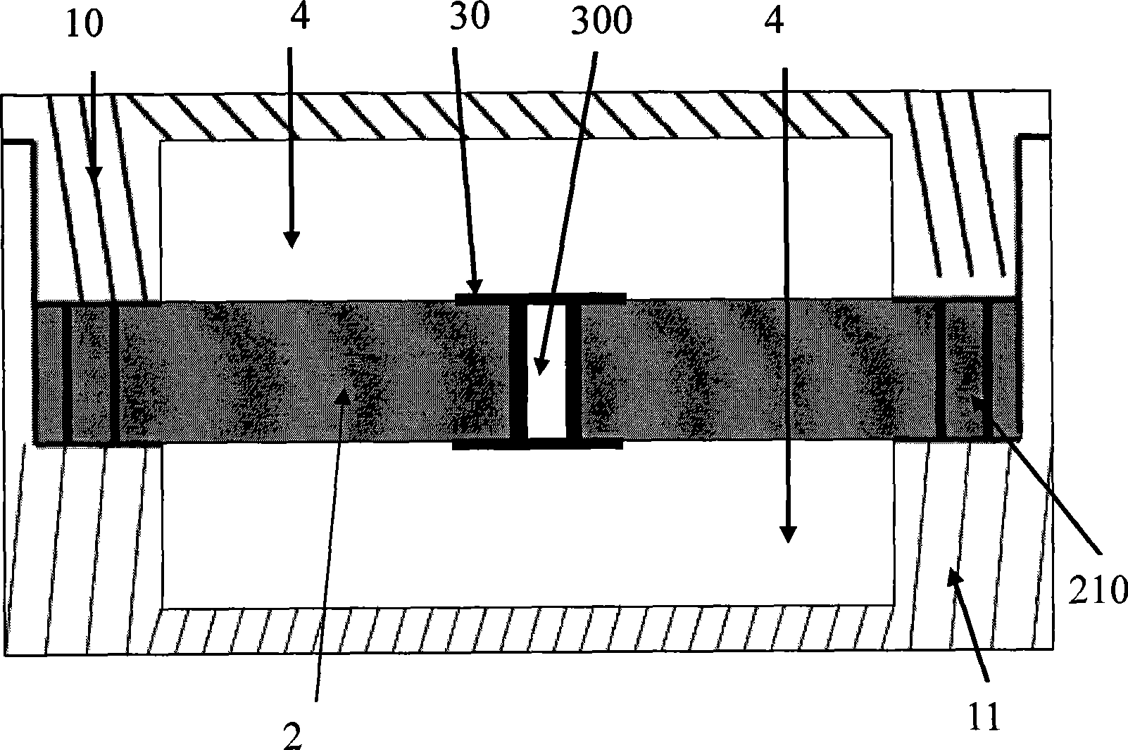
[0028] See image 3 Shown is a schematic diagram of a microstrip line filter in an embodiment of the present invention. The basic structure of the microstrip filter includes: a cavity formed by a metal shell, the cavity includes an upper cavity 10 and a lower cavity 11, a PCB double-sided panel 2 is arranged in the cavity, and the PCB double-sided panel 2 is fixed On the inner wall of the cavity, and there is a certain distance between the PCB double-sided board and the upper and lower inner walls of the metal shell, in one implementation, it is the air height; both sides of the PCB double-sided board are provided with (such as etching ) a ten-byte transmission line 30 with a predetermined shape as a filter, and the front and back ten-byte transmission lines 30 are communicated through at least one via hole 300 .

[0029] Such as Figure...


PUM


Abstract

The invention discloses a microstrip line filter, which comprises a chamber which is provided with a PCB plate; the top and bottom inner wall of the PCB plate and the chamber are provided with a certain air height; the two sides of the PCB plate are both provided with corresponding cross cascaded transmission line and the cross cascaded transmission line arranged on one side of the PCB plate is connected with the transmission line on the other side through a hole. The invention also discloses a corresponding duplexer and a radio-frequency device. The embodiment of the invention has the advantages of simple producing processing, high quality rate, low transmission loss, low cost, etc.

Description

technical field [0001] The invention relates to the technical field of communication, in particular to a microstrip line filter, a duplexer and a radio frequency device composed of the filter. Background technique [0002] With the rapid development of wireless communication technology, communication equipment of various frequency bands and standards are constantly appearing and put into use. In order to avoid mutual interference between signals of various communication systems, including the transmission and reception of their own systems, radio frequency filters are required for filtering. Especially on a radio frequency device (such as a wireless base station), in order to realize receiving and transmitting signals on the same antenna, a duplexer needs to be used. [0003] Such as figure 1 Shown is a structural schematic diagram of an existing duplexer; the duplexer adopts the form of a cavity dielectric filter. The geometry of the cavity determines the resonant frequen...

Claims


Application Information

Patent Timeline
Patent Type & Authority Applications(China)
IPC IPC(8): H01P1/203
Inventor 李新路何平华
Owner HUAWEI TECH CO LTD
Why Eureka
Try Eureka