Wastewater treatment device of horizontal polar plate multi-electrodes electrocatalysis reactor

A multi-dimensional electrode and wastewater treatment technology, which is applied in the direction of electrochemical water/sewage treatment, etc., can solve the problems of aeration effect, current efficiency unit space-time efficiency and treatment efficiency, unsatisfactory wastewater treatment effect, and low electrochemical oxidation speed. , to achieve the effect of improving the efficiency of electrolytic catalytic treatment, novel equipment structure and prolonging the service life

Active Publication Date: 2009-05-06
南京赛佳环保实业有限公司
View PDF5 Cites 44 Cited by
  • Summary
  • Abstract
  • Description
  • Claims
  • Application Information

AI Technical Summary

Problems solved by technology

Two-dimensional plate electrode equipment has disadvantages such as small area ratio, small space-time processing capacity, low current efficiency, high energy consumption, and high cost, and the effect of treating wastewater is not ideal.
However, the existing three-dimensional electrode electrocatalytic treatment equipment still has the problems of poor aeration effect, current efficiency, unit space-time efficiency and treatment efficiency for the treatment of high-concentration and refractory organic wastewater.
This is because the electrochemical oxidation rate of most refractory organics is generally relatively small

Method used


Image

  • Wastewater treatment device of horizontal polar plate multi-electrodes electrocatalysis reactor
  • Wastewater treatment device of horizontal polar plate multi-electrodes electrocatalysis reactor
  • Wastewater treatment device of horizontal polar plate multi-electrodes electrocatalysis reactor

Examples


Embodiment Construction

[0028] The present invention will be further described in detail below with reference to the accompanying drawings and examples. However, the invention is not limited to the examples given.

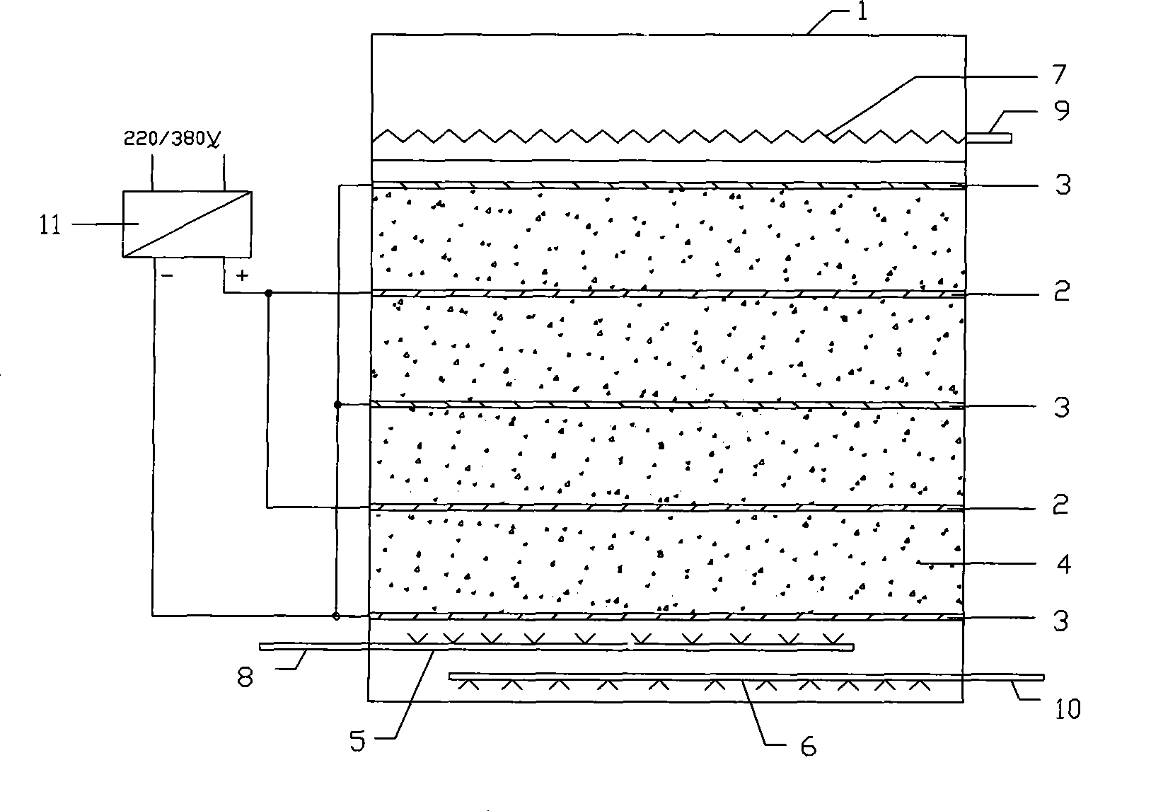
[0029] Such as figure 1 As shown, the horizontal plate multi-dimensional electrode electrocatalytic reactor wastewater treatment equipment of the present invention comprises a device housing 1, a parallel opposite cathode plate 3, an anode plate 2, particles filled between the cathode plate 3 and the anode plate 2 The electrode 4, the water distributor 5 and the water inlet pipe 8 connected thereto, the aerator 6 and the inlet pipe 10 connected thereto, the water outlet weir groove 7, the water outlet pipe 9 and the power supply 11, the cathode plate 3, the anode plate 2 and the power supply respectively Negative and positive connections, the improvement is that the cathode plate 3 and the anode plate 2 are distributed with a number of through holes (not shown in the figure), and the cat...


PUM

PropertyMeasurementUnit
pore sizeaaaaaaaaaa
particle diameteraaaaaaaaaa
porosityaaaaaaaaaa

Abstract

Horizontal polar plate multi-dimensional electrode electrocatalysis reactor wastewater treatment equipment comprises a shell, a cathode plate and an anode plate which are relatively parallel, a particle electrode filled between the cathode plate and the anode plate, a water distributor, a water inlet pipe, an aerator, an air inlet pipe, an effluent weir trough, a water outlet pipe and a power supply; the cathode plate and the anode plate are respectively connected with the cathode and the anode of the power supply; a plurality of through holes are distributed on the cathode plate and the anode plate which are horizontally positioned in the shell of the equipment; the water distributor, the water inlet pipe, the aerator and the air inlet pipe are positioned at the lower part of the shell of the equipment; and the effluent weir trough and the water outlet pipe are arranged at the upper part of the shell of the equipment. After being evenly distributed by the water distributor, the wastewater flows across a reactor from bottom to top; the horizontal polar plate structure design not only avoids the short circuit of water flow and improves the mass transfer effect, but also ensures that the wastewater can alternatively flow across the cathode plate and the anode plate and the oxidation reaction of the anode plate and the reduction reaction of the cathode plate coexist in a system, and causes different organic pollutants in wastewater which can be degraded by the oxidation reaction and the reduction reaction to be degraded and treated.

Description

technical field [0001] The invention relates to a device for treating high-concentration, poisonous and harmful organic waste water by means of chemical electrolysis and catalysis, and belongs to the technical field of electrochemical waste water treatment. Background technique [0002] Electrochemical method is an effective way to treat organic pollutants in wastewater. This method is a technical hotspot in the treatment of high-concentration organic wastewater today. [0003] The mechanism of electrochemical method to treat wastewater is to generate strong oxidizing substances (OH, H2O2, O2, etc.) in the reaction system, which will undergo direct oxidation and indirect oxidation reactions with organic pollutants, and decompose high-concentration, difficult-to-biodegrade macromolecular organic substances Become an easily biodegradable small molecule organic matter, improve the biodegradability of wastewater, and even completely mineralize it into inorganic substances such ...

Claims


Application Information

Patent Timeline
Patent Type & Authority Applications(China)
IPC IPC(8): C02F1/46
Inventor 刘秀宁汤捷杜小军
Owner 南京赛佳环保实业有限公司
Why Eureka
Try Eureka