Die quenching machine tool for numerical control force measurement

A technology of mold press quenching and machine tools, which is applied in quenching devices, heat treatment equipment, manufacturing tools, etc., to achieve the effect of meeting the oil entry time, avoiding erosion and pollution, and improving efficiency

Active Publication Date: 2010-08-11
张光荣
View PDF1 Cites 0 Cited by
  • Summary
  • Abstract
  • Description
  • Claims
  • Application Information

AI Technical Summary

Problems solved by technology

However, the above-mentioned equipment is a special quenching equipment that is hydraulically loaded and does not require precise control of displacement and load. For the quenching situation that has strict requirements on the quenching process, precise control of mold displacement and timely control of the pressure of the quenched workpiece, The above equipment is powerless

Method used


Image

  • Die quenching machine tool for numerical control force measurement
  • Die quenching machine tool for numerical control force measurement
  • Die quenching machine tool for numerical control force measurement

Examples


Embodiment 1

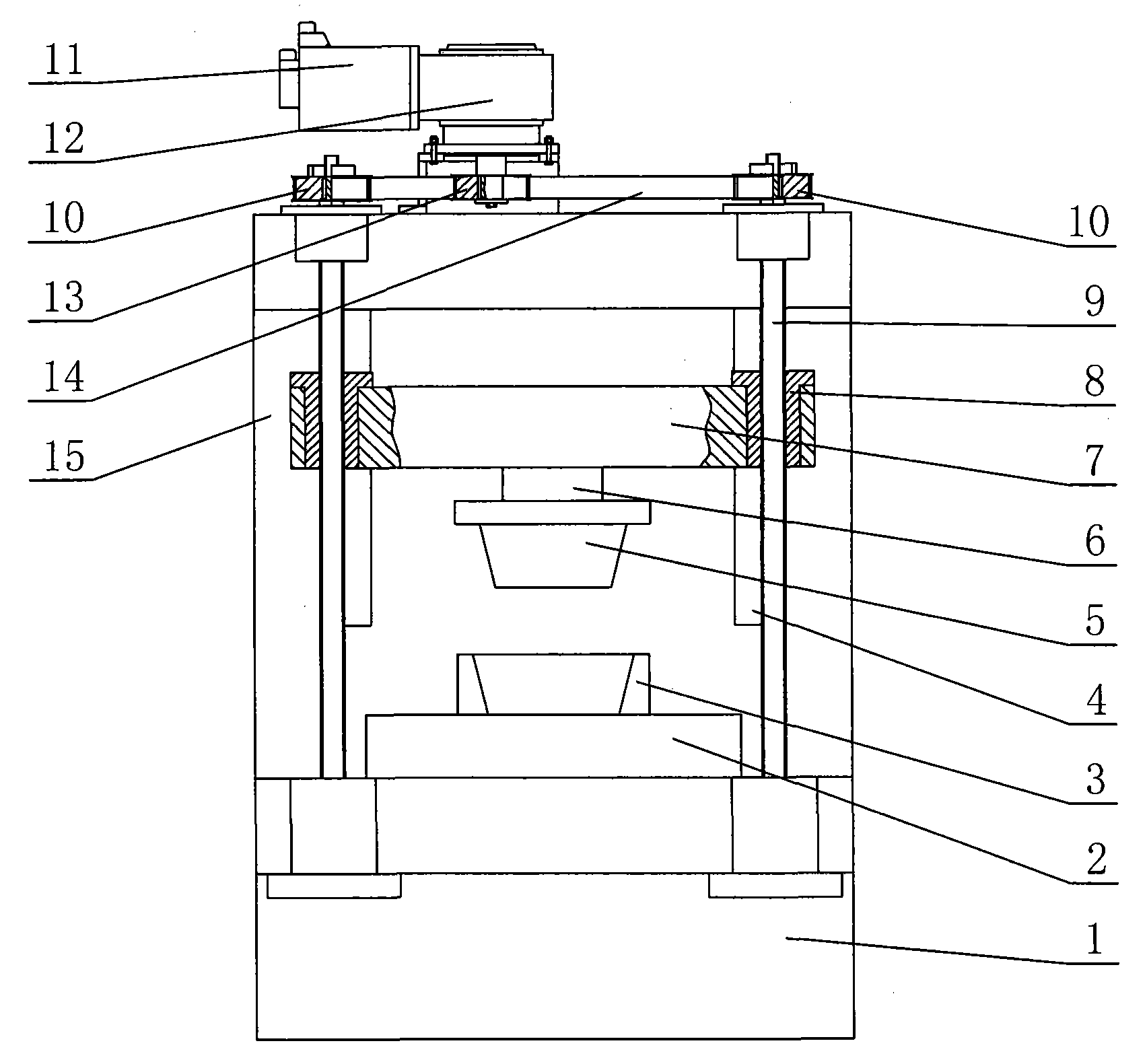
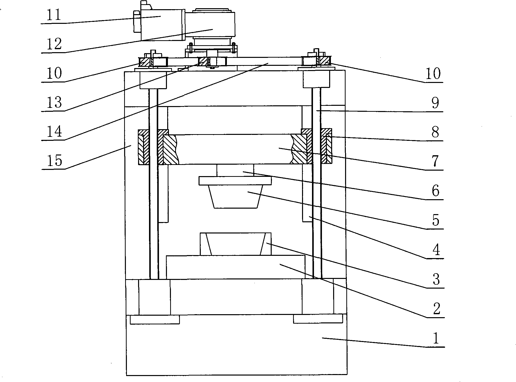
[0026] As shown in Figure 1, the quenching machine tool is a "door"-shaped double screw dragging quenching machine tool. The workbench 2 is installed on the base 1, and the lower mold 3 for fixing the workpiece to be quenched is installed on the workbench, and the upper mold 5 for fixing the workpiece to be quenched is installed on the moving beam 7 through the load cell 6, and the moving beam 7 Can move up and down along the vertical guide rail 4 on the lathe bed 15. A servo motor and a rotary encoder group 11 are installed on the upper part of the bed 15. The servo motor drives the reducer 12 to rotate. The toothed belt pulley 10 rotates, and the upper end of two passive toothed belt pulleys 10 and the ball screw 9 in the ball screw pair is connected by a key, and two nuts 8 in the ball screw pair are fixed on the left and right ends of the moving beam. When quenching, the workpiece to be quenched is installed in the lower mold. At this time, the servo motor-reducer-toothed...

Embodiment 2

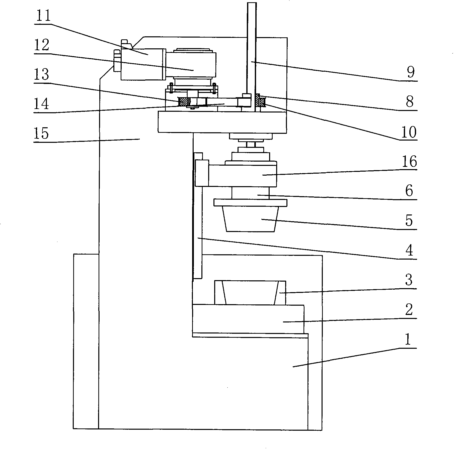
[0028] What this embodiment is aimed at is the quenching machine tool of " C " shape fuselage. As shown in Figure 2, the workbench 2 is installed on the base 1, and the lower mold 3 for fixing the workpiece to be quenched is installed on the workbench 2, and the upper mold 5 for fixing the workpiece to be quenched is installed on the slider through a load cell 6 16, the slide block 16 can move up and down along the vertical guide rail 4 on the machine bed 15. A servo motor and a rotary encoder group 11 are installed on the upper part of the bed 15. The servo motor drives the reducer 12 to rotate. The toothed pulley 10 rotates, and the nut 8 is coaxially installed on the driven toothed pulley 10. Since the nut 8 is axially fixed and can only rotate, the ball screw 9 moves up and down under the drive of the nut, and the lower end of the ball screw is rotatably connected with the slide block 16 . The transmission line during quenching is: servo motor-reducer-active toothed belt...

Embodiment 3

[0030] On the basis of Embodiment 1, the rotation of the ball screw is changed to the rotation of the nut, and the transmission of movement and force is changed from a double ball screw pair to a single ball screw pair, and the driven toothed pulley 10 is coaxially installed On the nut 8 in the ball screw pair, the lower end of the ball screw 9 is rotatably connected to the moving beam 7, and the rest of the structures remain unchanged.

[0031] In the above embodiments, the force sensor 6 can be a tension and pressure sensor.

[0032] The control system adopts computer control, which has the functions of timely data collection, digital display, storage, printing and network communication, and the quenching pressure of the whole quenching process is controlled by closed loop to control the corresponding relationship between the pressure and time applied to the quenched workpiece. Make the quenched workpiece always follow the designed quenching process curve during the quenchin...


PUM


Abstract

The invention relates to a heat treatment device, in particular to a transmission system for numerical control force-measuring mold-pressing quenching machine tools, which can accurately control pressure in a quenching process. In order to achieve the aim of the invention, the invention adopts a technical proposal that the transmission system for numerical control force-measuring mold-pressing quenching machine tools comprises a transmission device which is arranged on a machine tool and can drive an upper mold to move up and down, as well as a movable beam arranged on the upper mold; the transmission system is characterized in that the transmission device mainly comprises an actuating motor, a transmission chain and a ball screw pair; a ball screw is connected with the movable beam; a force-measuring sensor is arranged on the movable beam; signals of the force-measuring sensor are transmitted to a control system; and the actuating motor is electrically connected with the control system. The device controls the corresponding relationship between pressure applied to a quenched workpiece and time through closed-loop control, and ensures that the quenched workpiece is quenched alwaysaccording to a designed quenching process curve, which is undoubtedly a great technical promotion to the quenching of important parts.

Description

technical field [0001] The invention relates to a heat treatment device, in particular to a numerically controlled force-measuring die-press quenching machine tool which can precisely control the displacement of a mold during quenching, the pressure of the mold on a workpiece to be quenched, and maintain the pressure of the mold when the mold has zero displacement. Background technique [0002] During the quenching process, due to long-time heating and rapid cooling, the deformation of the quenched parts is unavoidable, especially for the inner and outer rings of thin-walled bearings, and various integrally quenched gears, this problem is particularly prominent. In order to solve the problems that the bearing and gear quenching process is uncontrollable, excessive deformation causes rework and high reject rate, people have done a lot of work, such as the inventor applied for "Railway Bearing Inner and Outer Ring Quenching Equipment" on April 10, 2006 ", the patent applicatio...

Claims


Application Information

Patent Timeline
Patent Type & Authority Patents(China)
IPC IPC(8): C21D1/62
Inventor 张光荣
Owner 张光荣
Why Eureka
Try Eureka