

Voltage orienting frequency conversion controller for open loop non-speed sensor
A speed sensorless, variable frequency controller technology, used in electronic commutation motor control, motor generator control, control of electromechanical brakes, etc., can solve the problems of light load oscillation and poor motor load capacity, and achieve smooth operation and output. The effect of torque enhancement and light-load oscillation suppression
- Summary
- Abstract
- Description
- Claims
- Application Information
AI Technical Summary
Problems solved by technology
Method used
Image

Examples
specific Embodiment approach 1
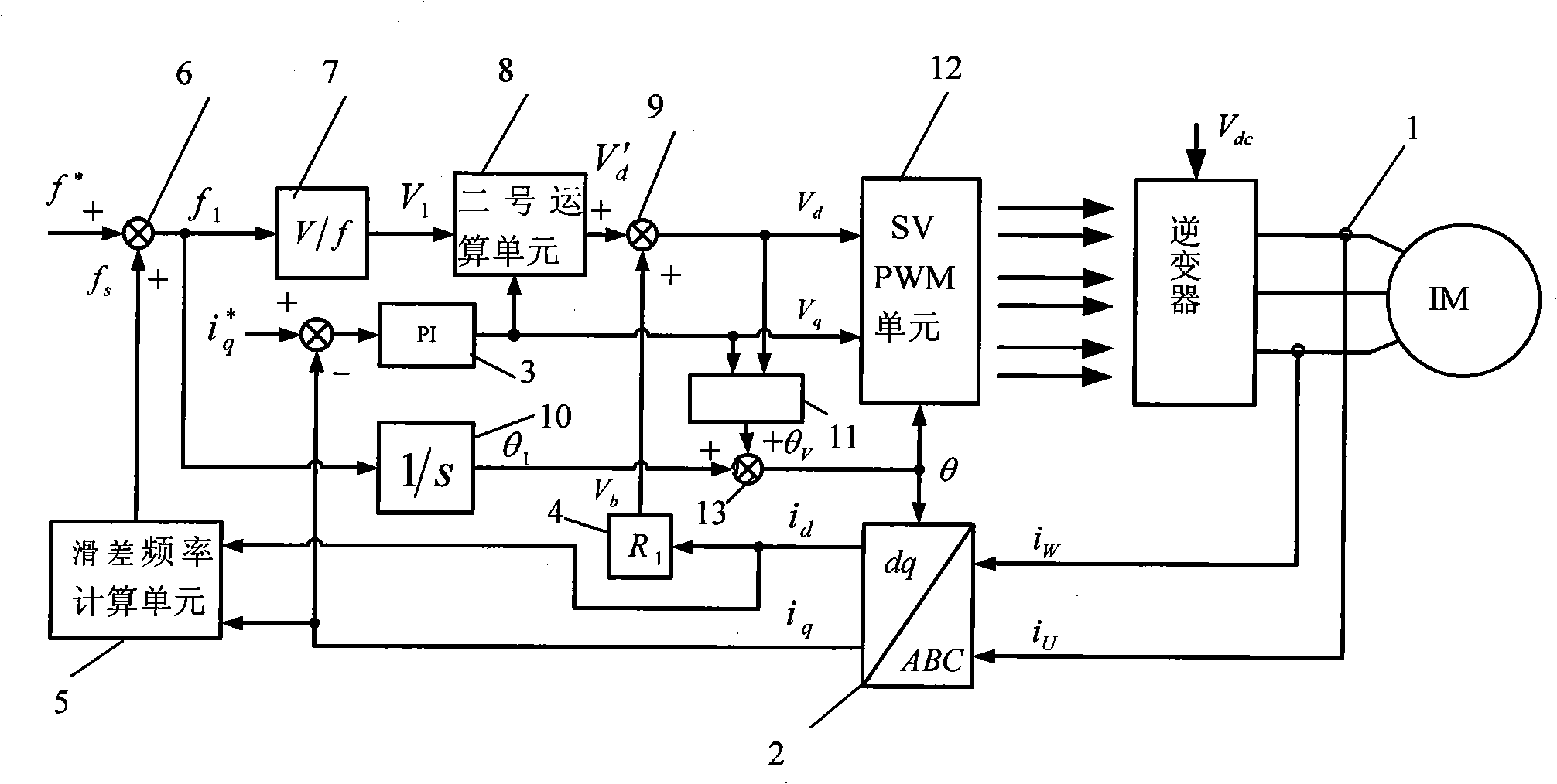
[0023] Specific implementation mode one: the following combination Figure 1 to Figure 3 This embodiment will be specifically described. The controller of the present invention is made up of the following units;
[0024] Current sensor 1: to detect the phase current on the stator of the induction motor IM through the current sensor 1;
[0025] Vector coordinate transformation unit 2: to realize the directional coordinate transformation of the induction motor IM stator voltage, and decompose the detected stator current into instantaneous active current i d and instantaneous reactive current i q ;
[0026] PI regulator 3: set the given reactive current i q * and instantaneous reactive current i q subtracted as the input of PI regulator 3, the output voltage of the PI regulator V q As the q-axis voltage given value of SVPWM unit 12, to utilize PI regulator 3 to instantaneous reactive current i q Feedback control is performed so that the reactive current on the stator of t...
specific Embodiment approach 2
[0061] Specific implementation mode two: the following combination Figure 4 to Figure 9 A specific example is given. This embodiment adopts controller of the present invention and an inverter and an induction motor, and the parameter of this motor is as follows: rated voltage: 380V, rated current 15.4A, rated power is 7.5Kw, rated speed is 1440r / min, rated frequency It is 50Hz, the stator resistance is 0.611Ω, the rotor resistance is 0.434Ω, the excitation inductance is 105.6mH, and the stator leakage inductance is 2.32mH. Figure 4 It is the current waveform of the motor when it is no-load. From the figure, it can be seen that the motor current is stable and there is no oscillation phenomenon when it is no-load. Figure 5 It is the motor current waveform when starting with full load. It can be seen from the figure that the motor has a strong load capacity and quick response, and the current in the second cycle reaches a stable operating current. Figure 6 It is the motor c...
PUM
 Abstract
Description
Claims
Application Information