Power converting apparatus

A power conversion device and electric power technology, applied in the direction of output power conversion device, electrical components, AC power input conversion to DC power output, etc., can solve the problems of increased electromagnetic noise, increased system reactance, increased power loss, etc.

Inactive Publication Date: 2009-05-13
MITSUBISHI ELECTRIC CORP
View PDF0 Cites 16 Cited by
  • Summary
  • Abstract
  • Description
  • Claims
  • Application Information

AI Technical Summary

Problems solved by technology

If higher harmonics are to be suppressed without distortion for waveform formation, it is necessary to increase the reactance (reactor) of the system, or increase the number of switching
However, if the reactance is increased, the size of the device will increase, and if the number of switching times increases, the power loss will increase and the electromagnetic noise will also increase.
In addition, if the number of switching is reduced, the current distortion increases, and there is a problem that the system will generate high-order harmonic currents

Method used


Image

  • Power converting apparatus
  • Power converting apparatus
  • Power converting apparatus

Examples


Embodiment 1

[0042] Hereinafter, a power conversion device according to Embodiment 1 of the present invention will be described with reference to the drawings.

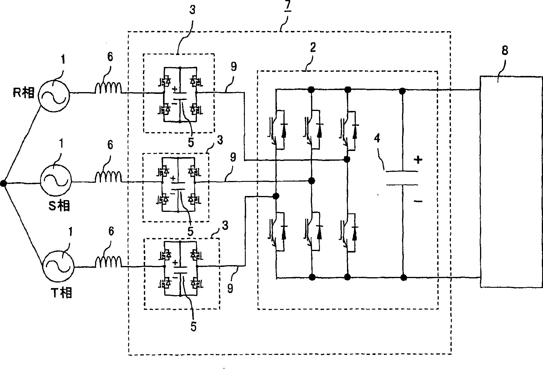
[0043] figure 1 It is a figure which shows the structure of the power conversion apparatus of Example 1 of this invention.

[0044] Such as figure 1 As shown, the power conversion device is composed of a power converter 7 in which the AC side of the single-phase sub-converter 3 is connected in series to the main converter 2 constituted by a three-phase two-level converter. Each phase is formed on the AC input line 9. The main converter 2 and each sub-inverter 3 include filter capacitors 4 and 5 on the DC output side, and the filter capacitor 4 of the main converter 2 and the filter capacitor 5 of the sub-inverter 3 have different DC voltages. The power converter 7 converts the AC power supplied from the three-phase AC system power supply 1 as an AC power source through the system reactor 6 into DC power, and supplies the DC pow...

Embodiment 2

[0085] Figure 17 is a diagram showing a control flow of the power conversion device according to Embodiment 2 of the present invention. The main circuit structure and figure 1 , figure 2 Same as Example 1 shown.

[0086] In the DC voltage control 70 of the sub-inverter, the measured DC voltage Vb of the sub-inverter 3 is compared with the set DC voltage command value Vb0 to determine whether the DC voltage Vb is increasing or decreasing (step 72), and the input The current command amplitude of the system current is determined to be power running or regeneration (step 74), and the pulse width of the system current is determined and output (step 73). In the current control 71, it is determined whether the DC voltage Vc of the main converter 2 is increasing or decreasing (step 75), thereby increasing or decreasing the amplitude of the current command and inputting it to step 74, and the current command is also increased or decreased (step 76).

[0087] In such control, by a...

Embodiment 3

[0095] Next, a power conversion device according to Embodiment 3 of the present invention will be described with reference to the drawings.

[0096] The main circuit structure and figure 1 , figure 2Same as Example 1 shown. In addition, in the smoothing capacitor 5 of the sub-inverter 3 , measures to stabilize the voltage are required, but here, for convenience, the description thereof is omitted, and it is assumed that the voltage has already been stabilized.

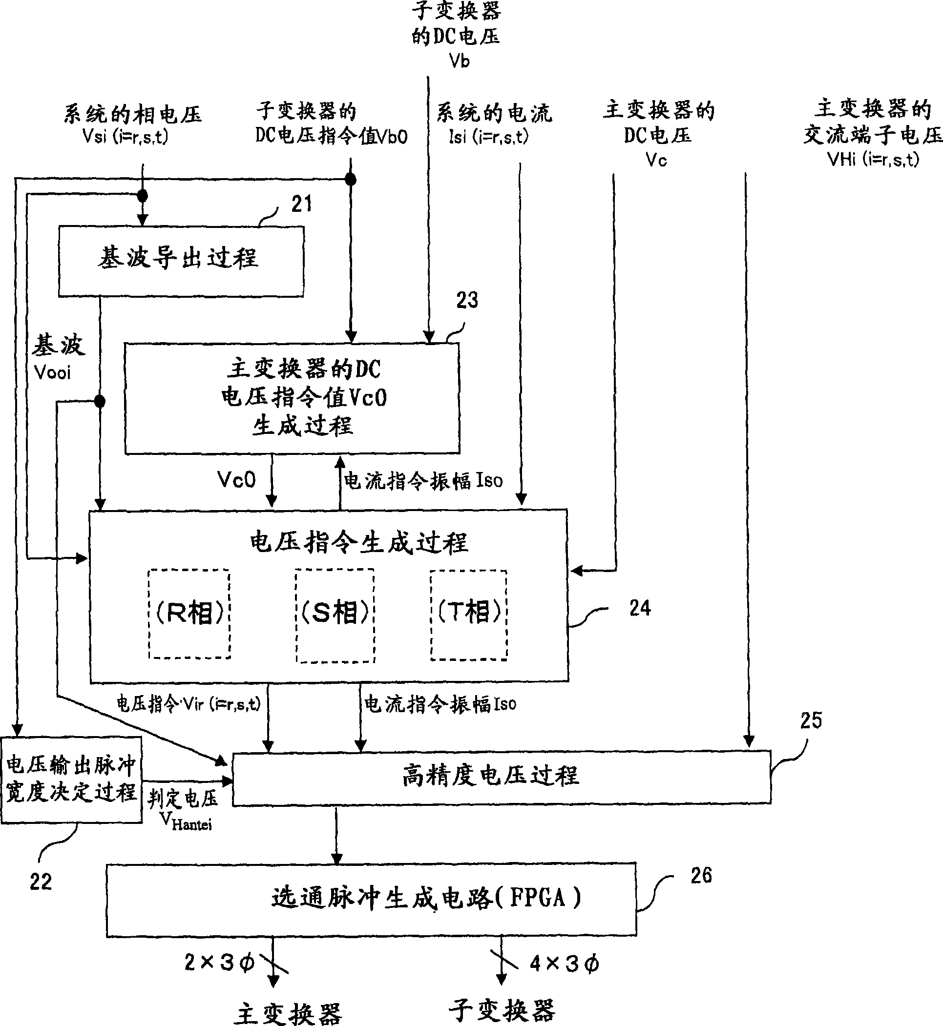
[0097] Figure 20 It is a diagram showing the entire control flow of the power conversion device according to Embodiment 3 of the present invention.

[0098] Such as Figure 20 As shown, in the voltage output pulse width determination process 22a, the fundamental wave Vooi of the system voltage is derived from the measured phase voltage Vsi (i=r, s, t) of the system power supply 1, and the filter capacitor of the sub-converter 3 The voltage (DC voltage) Vb determines the pulse width of the gate signal that drives...


PUM


Abstract

The invention provides a converter controllable in regenerative running mode, which is a power converting apparatus capable of suppressing harmonics without increasing the size of a reactor, and reducing power loss and electromagnetic noise. A power converter (7) is configured by directly connecting AC sides of single-phase sub-converters (3) having a DC voltage lower than a DC voltage of a 3-phase main converter (2) to AC input lines of individual phases thereof in series. The main converter (2) is driven by one gate pulse per half recurring cycle and a voltage produced by each sub-converter (3) at AC terminals thereof is controlled to match a difference between an AC power supply voltage and a voltage produced by the main converter (2) at AC terminals thereof, whereby phase voltages of the power converter (7) are generated as the sums of phase voltages of the individual converters (2), (3).

Description

technical field [0001] The present invention relates to a power conversion device, and more particularly to a converter for converting AC power into DC power. Background technique [0002] As an existing power conversion device, a PWM converter composed of semiconductor elements with self-arc suppression capabilities such as GTO can perform switching regardless of the polarity of the power supply voltage, the polarity of the current, and the magnitude. It can be controlled to force rate 1, and can be controlled to force rate -1 during regeneration (for example, refer to Non-Patent Document 1). [0003] Non-Patent Document 1: "Latest Electric Railway Engineering" (published by Corona Corporation on September 11, 2000, by the Electric Railway Research Committee of the Institute of Electrical Engineering) P60-67 [0004] However, in a conventional PWM converter, a voltage is generated at an AC input terminal by PWM control of a pulse with a large voltage. If higher harmonics ...

Claims


Application Information

Patent Timeline
Patent Type & Authority Applications(China)
IPC IPC(8): H02M7/12H02M1/12
CPCH02M1/12H02M2001/007H02M7/797H02M1/007H02M1/0095H02M7/12
Inventor 岸田行盛岩田明彦小草慎一金中晶长野铁明
Owner MITSUBISHI ELECTRIC CORP
Why Eureka
Try Eureka