Horizontal type swirl machining center

A machining center, horizontal technology, applied in the direction of metal processing, metal processing equipment, metal processing machinery parts, etc., can solve the problems of difficult to guarantee precision milling, clearance and error, difficulty in chip removal of machine tools, etc., to eliminate processing errors, Ease of chip removal and ensure machining accuracy

Inactive Publication Date: 2009-05-20
GUANGZHOU CITY AGILE MFG
View PDF0 Cites 4 Cited by
  • Summary
  • Abstract
  • Description
  • Claims
  • Application Information

AI Technical Summary

Problems solved by technology

For general machining accuracy, this error is negligible, but for vortex machining, which requires such a high profile, this error is fatal and not allowed, so the principle of linear coordinate interpolation is adopted The existing machine tools cannot meet the requirements of the existing scroll compressor turbine processing; in addition, the existing processing equipment is a vertical machining center, which is difficult to remove chips from the machine tool, and the iron chips are likely to affect the surface finish of the workpiece; there is also the existing processing equipment When machining parts, the main shaft is used to change the tool. The same main shaft is used for rough milling and fine milling. When the main shaft is changed, there will be gaps and errors, so the accuracy of fine milling is difficult to guarantee.

Method used


Image

  • Horizontal type swirl machining center
  • Horizontal type swirl machining center
  • Horizontal type swirl machining center

Examples


Embodiment Construction

[0022] The present invention will be further described below in conjunction with accompanying drawing.

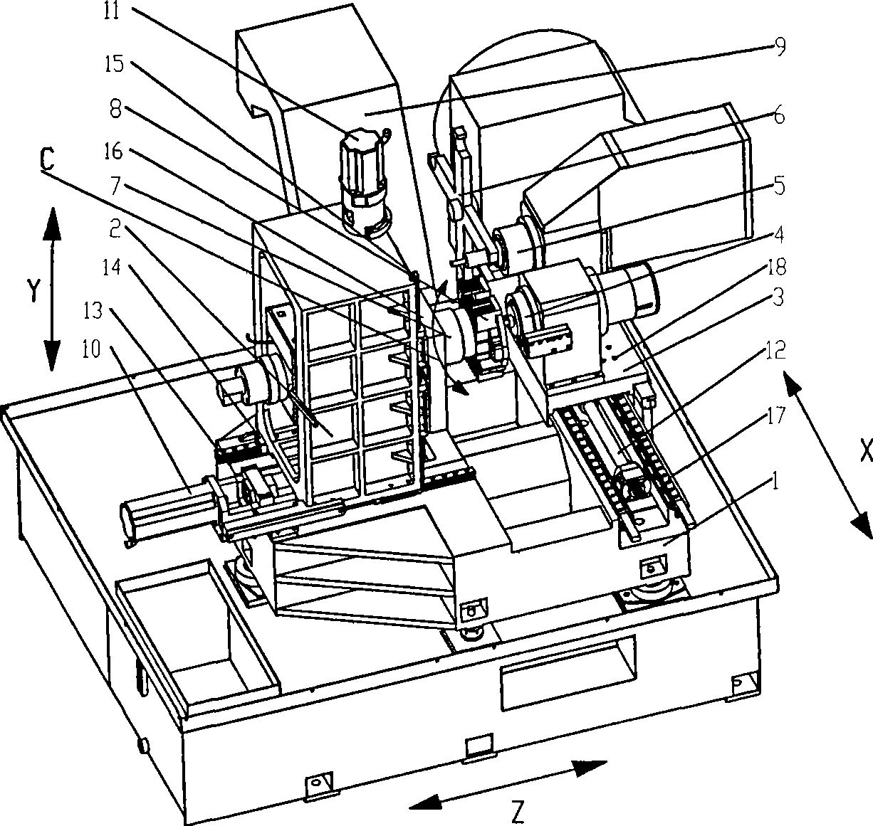
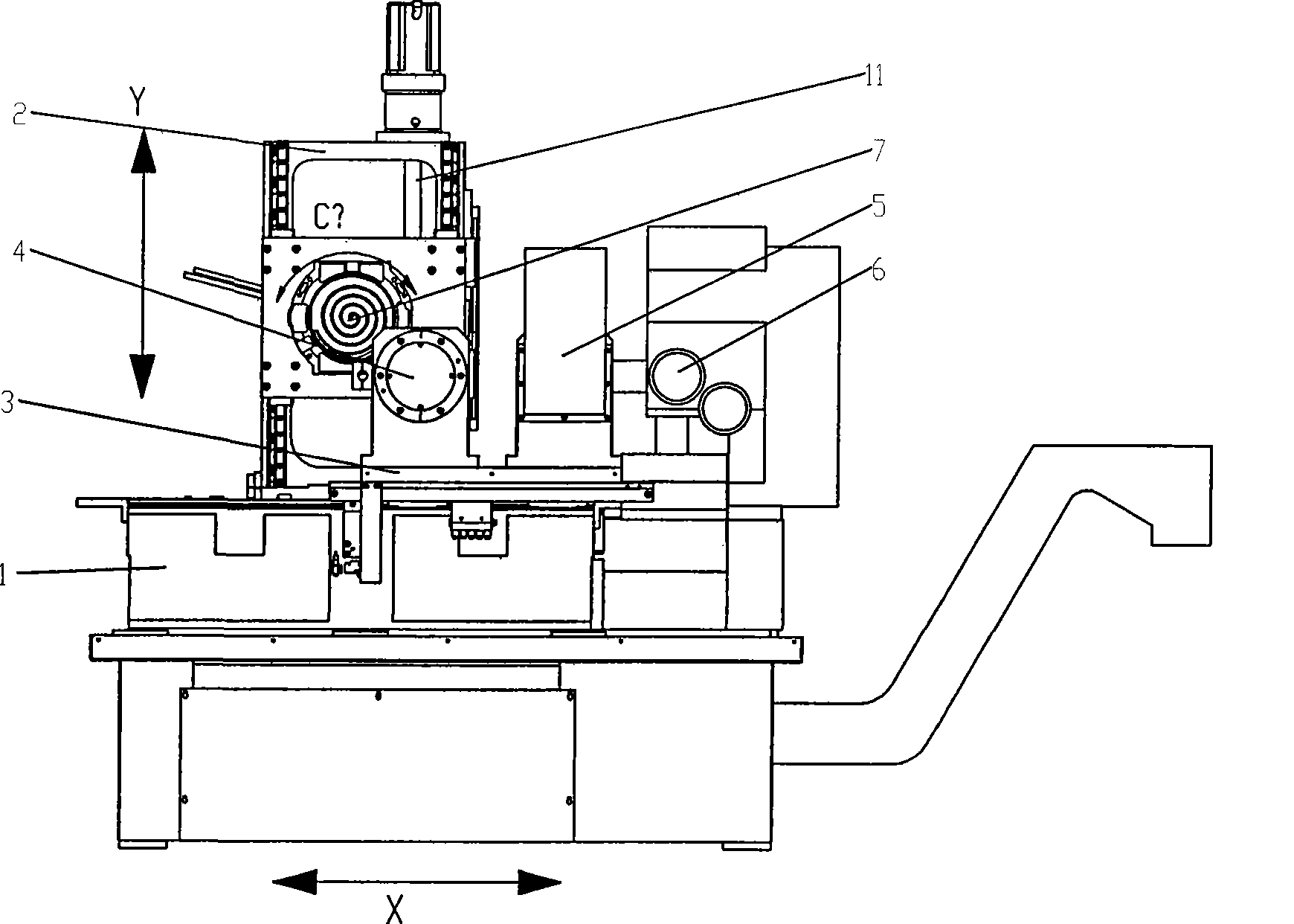
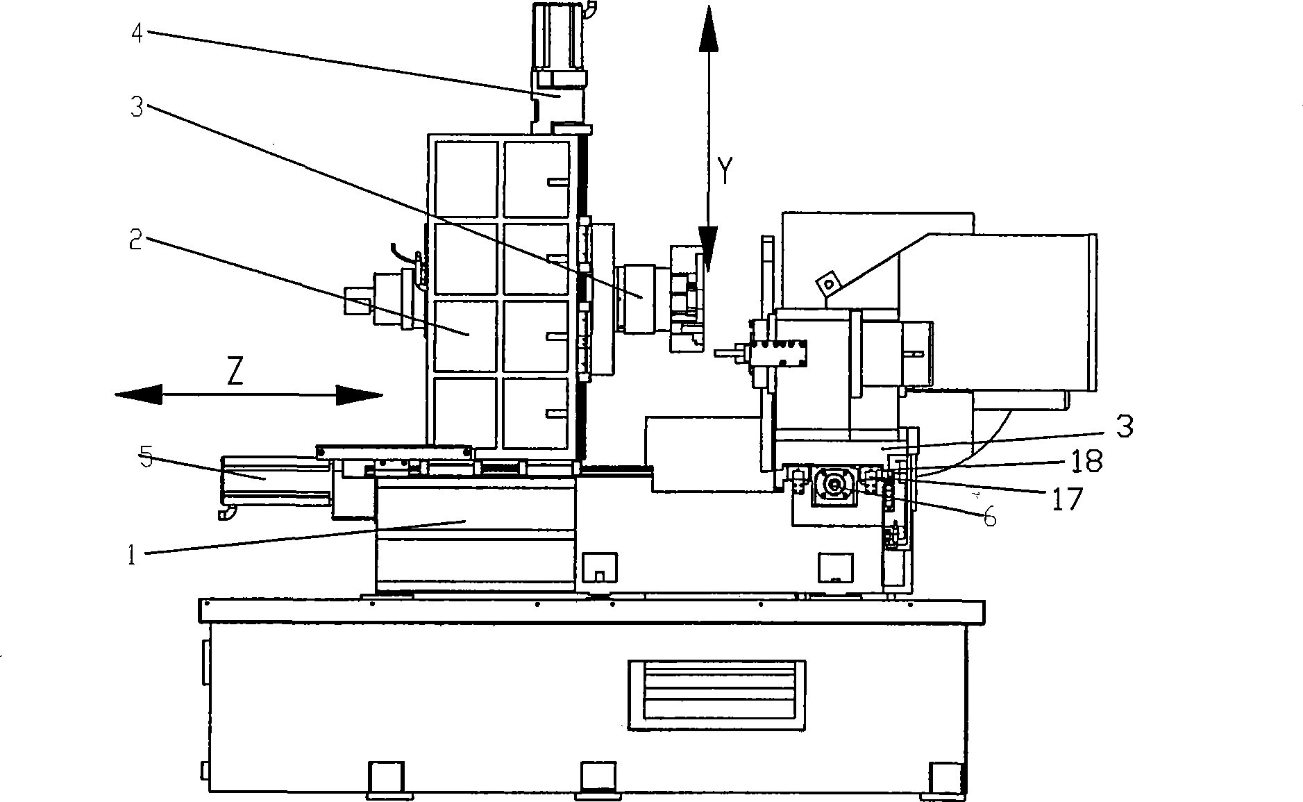
[0023] In the figure: bed 1, column 2, X-direction slide 3, precision milling electric spindle 4, machining center spindle 5, machining center tool magazine 6, workpiece torque motor spindle 7, scroll parts 8, chip conveyor 9, Z Direction servo drive unit 10, Y direction servo drive unit 11, X direction servo drive unit 12, Z direction guide rail 13, Z direction slider 14, Y direction guide rail 15, Y direction slider 16, X direction guide rail 17, X direction slide Block 18.

[0024] as attached figure 1 , attached figure 2 , attached image 3 , attached Figure 4 As shown, the present invention is composed of a bed 1, a column 2, an X-direction slide plate 3, a precision milling spindle 4, a machining center spindle 5, a machining center tool magazine 6, a workpiece torque motor spindle 7, a chip conveyor 9, and a Z-direction servo drive. Unit 10, Y-direction servo ...


PUM


Abstract

The invention relates to a horizontal vortex machining center, which relates to a high-grade digital control machine tool product for processing a key component of a vortex compressor. The horizontal vortex machining center consists of a lathe bed, an upright post, a precise milling electrical main shaft, a machining center main shaft, a machining center tool magazine, a workpiece moment motor main shaft, a Z-axis guide rail, a Z-axis slider, a Y-axis guide rail, a Y-axis slider, an X-axis guide rail, an X-axis slider, etc., wherein the X-axis guide rail is arranged on the lathe bed; the precise milling electrical main shaft is arranged on the X-axis slider; the Z-axis guide rail is arranged on the lathe bed; the upright post is arranged on the Z-axis slider; the Y-axis guide rail is arranged on the upright post; the workpiece moment motor main shaft is arranged on the Y-axis slider; the machining center main shaft is arranged on the X-axis slider; the workpiece moment motor main shaft is a C gyro shaft and horizontally arranged on the Y-axis slider. The horizontal vortex machining center guarantees the precision requirement of workpieces, is easy to remove scrap iron, and avoids influence on the surface quality of the workpieces due to accumulation of the scrap iron.

Description

technical field [0001] The invention relates to a horizontal scroll machining center, which relates to a high-grade numerically controlled machine tool product used for machining key components of a scroll compressor, in particular to a horizontal scroll machining center based on polar coordinate interpolation. Background technique [0002] The scroll compressor is the third generation compressor, and it is a brand-new variable cross-section scroll structure type compressor, which is a leap in compressor technology. The core component rotor of the scroll compressor has an involute The curved surface connected with the arc curve requires a profile of 0.008mm, which has particularly high requirements for processing equipment. The existing processing equipment is a high-speed vertical machining center with three-axis linkage. The machine tool has three linear axes of X, Y, and Z, which are rectangular coordinates. The main shaft adopts an electric spindle. This traditional X, Y...

Claims


Application Information

Patent Timeline
Patent Type & Authority Applications(China)
IPC IPC(8): B23Q1/01B23Q5/00B23Q11/00
Inventor 赵虎谢政平
Owner GUANGZHOU CITY AGILE MFG
Why Eureka
Try Eureka