Pneumatic lever type clamping structure

A lever-type and fixture technology, which is applied in clamping, manufacturing tools, supports, etc., can solve the problems of different sizes, different loading and unloading methods, and large locking force, so as to achieve stable processing cycle, improve processing accuracy, and use safely. convenient effect

Inactive Publication Date: 2009-05-20
THIXOMAG TECHNOLOGH WUHU
View PDF0 Cites 21 Cited by
  • Summary
  • Abstract
  • Description
  • Claims
  • Application Information

AI Technical Summary

Problems solved by technology

[0002] In the fixtures for steering wheels and steering columns of automobiles that process light alloy materials, most of the structures used are: manual quick clamping; or bolt locking; or cylinder compression and other clamping methods, but these clamping methods are not suitable for use by CNC. CNC special machine tools are used to process the steering wheel and steering column parts of light alloy materials. The reason is that manual quick clamps are used for clamping. The disadvantage is that the rubber head is easily damaged and the clamping is not tight. If it is replaced by iron or copper If the contact is of high quality, it will not be clamped tightly due to the lack of elasticity and cushioning force of the contact; bolt locking: this method is better, and the locking force is greater, but the efficiency is too low to adapt to modern processing equipment with a high degree of automation Cylinder compression: choose a cylinder and directly use the cylinder to compress, although this method is feasible, but because the pressure of different cylinders is different, the energy consumption is different, and the size is different, the use, loading and unloading methods, etc. Aspects will cause a large difference, and the price gap is large

Method used


Image

  • Pneumatic lever type clamping structure
  • Pneumatic lever type clamping structure

Examples


Embodiment 1

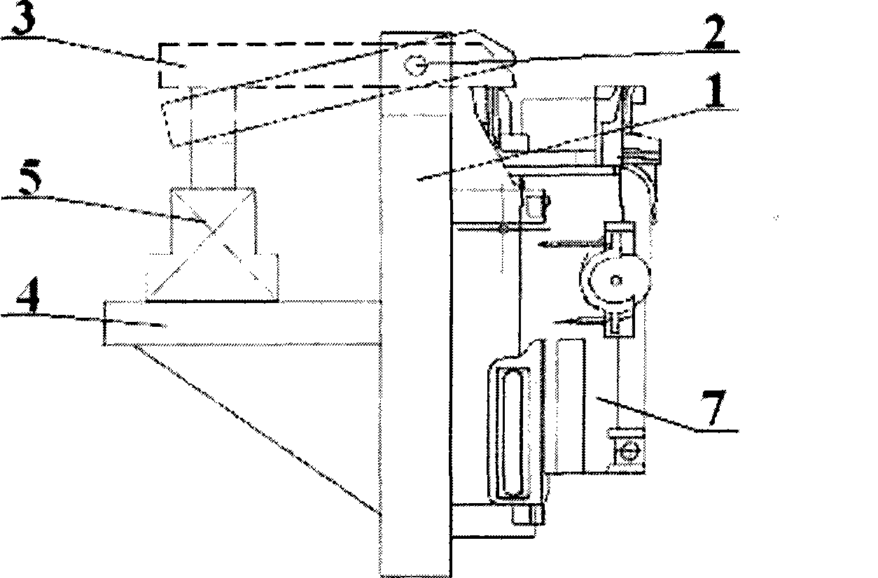
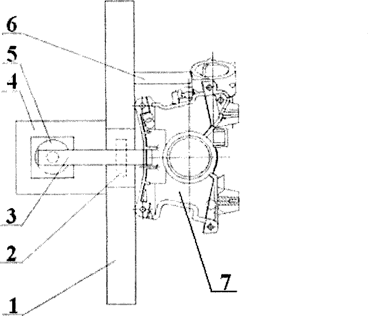
[0023] The distance between the lever fulcrum 2 of the present invention and the connection position between the pressure plate 3 and the cylinder 5 is the arm of force; the distance between the lever fulcrum 2 and the contact position between the pressure plate 3 and the workpiece 7 is the action arm; the length of the force arm is greater than The length of the action arm.

[0024] In increasing the fast clamping effect on the workpiece, the leverage principle is used to increase the force of the cylinder.

Embodiment 2

[0026] When the pressing plate 3 of the present invention clamps the workpiece 7, the end point of the cylinder 5 pushes the force arm to move upward, that is, the workpiece 7 is below the force arm.

[0027] Depend on figure 1 , figure 2 Visible, the using method of the present invention is: first the steering wheel steering column is clamped on the clamp body 1; The cylinder 5 exerts a force on the pressure plate 3 with the lever fulcrum 2 as the fulcrum, thereby effectively limiting the vertical freedom of the steering column Z axis and fixing its processing position.

[0028] This kind of pneumatic lever clamp structure uses an external cylinder to design a lever fulcrum between the workpieces to be processed, so that the work done by the external cylinder can generate enough force to quickly clamp the workpiece through the formed active arm. If such light alloy castings are processed by modern CNC machine tools, this pneumatic lever clamp structure is very practical an...


PUM


Abstract

The invention discloses a pneumatic lever type clamp structure. A pressure plate (3) is a lever structure, and the gyration center of the pressure plate is hinged with a clamp body (1) through a lever fulcrum (1); and under the state that a workpiece (7) is tightly clamped, one end of the pressure plate (3) is connected with a piston rod on a cylinder (5), while the other end is contacted with the clamped workpiece (7). With the technical proposal, pressing force of the cylinder can be increased through an arm of the lever structure by the lever principle when the cylinder is adopted, so that the processing workpiece can be pressurized conveniently and more effectively. The invention has a simple structure, can effectively improve the efficiency of processing parts, can realize stable processing tempo, and has the advantages of high rate of finished products and safe and convenient use.

Description

technical field [0001] The invention relates to a pneumatic lever type fixture structure for clamping workpieces. Background technique [0002] In the fixtures for steering wheels and steering columns of automobiles that process light alloy materials, most of the structures used are: manual quick clamping; or bolt locking; or cylinder compression and other clamping methods, but these clamping methods are not suitable for use by CNC. CNC special machine tools are used to process the steering wheel and steering column parts of light alloy materials. The reason is that manual quick clamps are used for clamping. The disadvantage is that the rubber head is easily damaged and the clamping is not tight. If it is replaced by iron or copper If the contact is of high quality, it will not be clamped tightly due to the lack of elasticity and cushioning force of the contact; bolt locking: this method is better, and the locking force is greater, but the efficiency is too low to adapt to m...

Claims


Application Information

Patent Timeline
Patent Type & Authority Applications(China)
IPC IPC(8): B23Q3/06
Inventor 徐章跃黄海吴仁荣张建军
Owner THIXOMAG TECHNOLOGH WUHU
Why Eureka
Try Eureka