Air source heat pump system capable of continuously supplying heat by refrigerant super cooling defrost

An air source heat pump and refrigerant technology, which is applied in heat pumps, refrigerators, refrigeration components, etc., can solve the problems of drastic changes in suction pressure, stop heating, and reduce heat supply, so as to reduce drastic changes and eliminate the impact. , Improve the effect of suction superheat

Inactive Publication Date: 2009-05-20
HARBIN INST OF TECH
View PDF0 Cites 13 Cited by
  • Summary
  • Abstract
  • Description
  • Claims
  • Application Information

AI Technical Summary

Problems solved by technology

[0003] In order to solve the problems of the existing defrosting method in the defrosting process, the suction pressure changes sharply, the heat supply to the room is reduced, the heat suppl

Method used


Image

  • Air source heat pump system capable of continuously supplying heat by refrigerant super cooling defrost

Examples


specific Embodiment approach 1

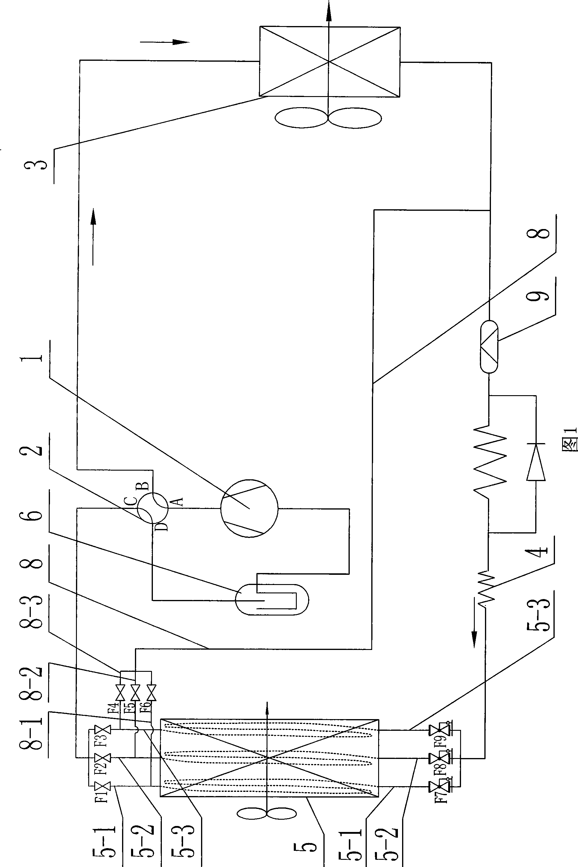
[0007] Specific Embodiment 1: As shown in Figure 1, the air source heat pump system for continuous heating using refrigerant subcooling and defrosting described in this embodiment includes a compressor 1, a four-way reversing valve 2, an indoor unit 3, Throttle mechanism 4, outdoor unit 5 and gas-liquid separator 6, the air source heat pump system also includes a first solenoid valve F1, a second solenoid valve F2, a third solenoid valve F3, a seventh pressure reducing valve F7, an eighth pressure reducing valve Pressure valve F8, ninth pressure reducing valve F9 and defrosting branch assembly; the defrosting branch assembly consists of the fourth solenoid valve F4, the fifth solenoid valve F5, the sixth solenoid valve F6, the defrosting branch 8, the A branch road 8-1, a second branch road 8-2 and a third branch road 8-3 are formed; the first branch road 8-1 is provided with a sixth electromagnetic valve F6, and the second branch road 8-2 is provided with The fifth solenoid v...

specific Embodiment approach 2

[0009] Embodiment 2: As shown in FIG. 1 , the air source heat pump system in this embodiment further includes a dryer 9 , and the dryer 9 is arranged on the pipeline between the indoor unit 3 and the throttling mechanism 4 . The drier 9 can remove substances such as moisture in the refrigerant. Other components and connections are the same as those in the first embodiment.

[0010] working principle:

[0011] When the heat pump is in the heating state, the first solenoid valve F1, the second solenoid valve F2, the third solenoid valve F3, the seventh pressure reducing valve F7, the eighth pressure reducing valve F8 and the ninth pressure reducing valve F9 are kept open, The fourth solenoid valve F4, the fifth solenoid valve F5 and the sixth solenoid valve F6 are kept closed; the high-temperature (high-pressure) gas refrigerant discharged by the compressor 1 is turned into a low-temperature and low-pressure liquid state by the throttling mechanism 4 after the heat release of t...


PUM


Abstract

The invention discloses an air source heat pump system for continuous heat supply through utilizing the undercooling and defrosting of a cryogen and relates to an air source heat pump system. The system effectively solves the problems that the prior defrosting mode has drastic change of air suction pressure, reduces the heating load indoors, stops heat supply indoors and blows cold wind indoors in the defrosting process. The outlet end of a compressor is communicated with a first port of a four-way reversing valve; a second port of the four-way reversing valve is communicated with the inlet end of an indoor machine; the outlet end of the indoor machine is respectively communicated with one end of a first bypass shunt circuit, one end of a second bypass shunt circuit and one end of a third bypass shunt circuit; one end of the first bypass shunt circuit is provided with a seventh decompression valve; one end of the second bypass shunt circuit is provided with an eighth decompression valve; and one end of the third bypass shunt circuit is provided with a ninth decompression valve. The system realizes unintermittent heat supply in the defrosting process, reduces drastic change of air suction pressure of the compressor, is more stable in the conversion process of heat supply and defrosting and well removes the influence on the heating load indoors in the prior hot air bypass defrosting.

Description

technical field [0001] The invention relates to an air source heat pump system. Background technique [0002] As an energy-saving and environment-friendly heating method, air source heat pump has received more and more attention. However, during operation, there is frost on the outdoor unit of the unit. The existence of the frost layer seriously affects the heating performance of the unit. Therefore, it is necessary to remove the frost layer in time. How to achieve timely and effective defrosting has become an urgent research problem. There are many existing defrosting methods, but they all have different degrees of problems. In summary, there are mainly the following problems: 1. Natural defrosting method, the compressor needs to be interrupted during defrosting, and the outdoor air temperature is required to be higher than 2-3 °C Only when it can run, the limitation is big. 2. The electric heating defrosting method consumes high-quality electric energy, the energy uti...

Claims


Application Information

Patent Timeline
IPC IPC(8): F25B13/00F25B30/06F25B47/02
Inventor 姜益强姚杨马最良董建锴
Owner HARBIN INST OF TECH
Why Eureka
Try Eureka