Coated glass pane

A glass plate, coating technology, applied in the direction of thin material handling, transportation and packaging, etc., can solve the problem of unsatisfactory resistance to mechanical and chemical influences, etc.

Active Publication Date: 2009-05-20
PILKINGTON GROUP LTD +1
View PDF11 Cites 12 Cited by
  • Summary
  • Abstract
  • Description
  • Claims
  • Application Information

AI Technical Summary

Problems solved by technology

[0011] In particular it was found that coatings with Zn-Sn oxide anti-reflection layers progressively show relatively high haze values ​​during heat treatment at temperatures above 650 °C, whereas coatings with silicon(oxy)nitride anti-reflection layers show Unsatisfactory robustness against mechanical and chemical influences (robustness)

Method used


Image

  • Coated glass pane
  • Coated glass pane
  • Coated glass pane

Examples


Embodiment 1

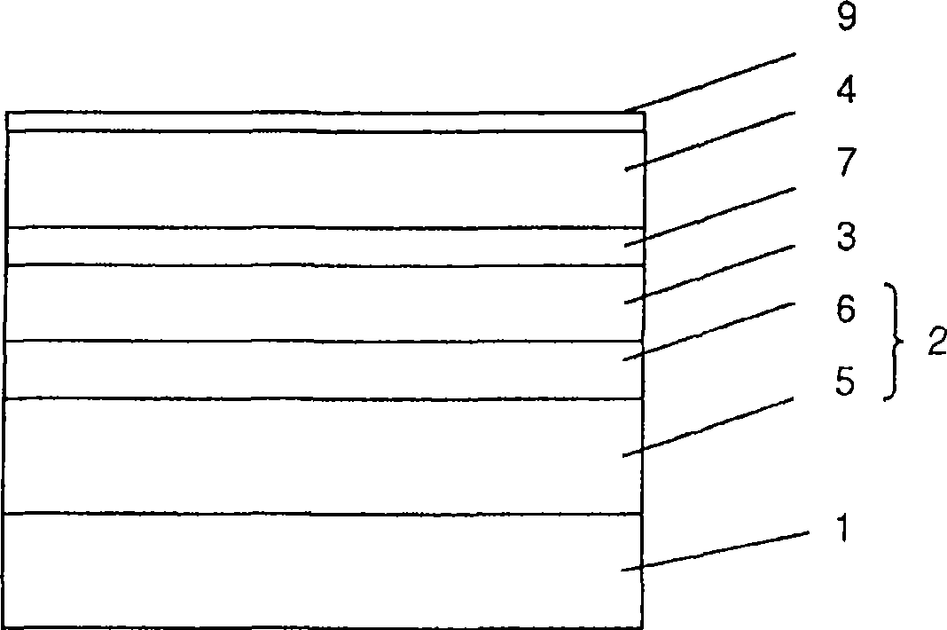
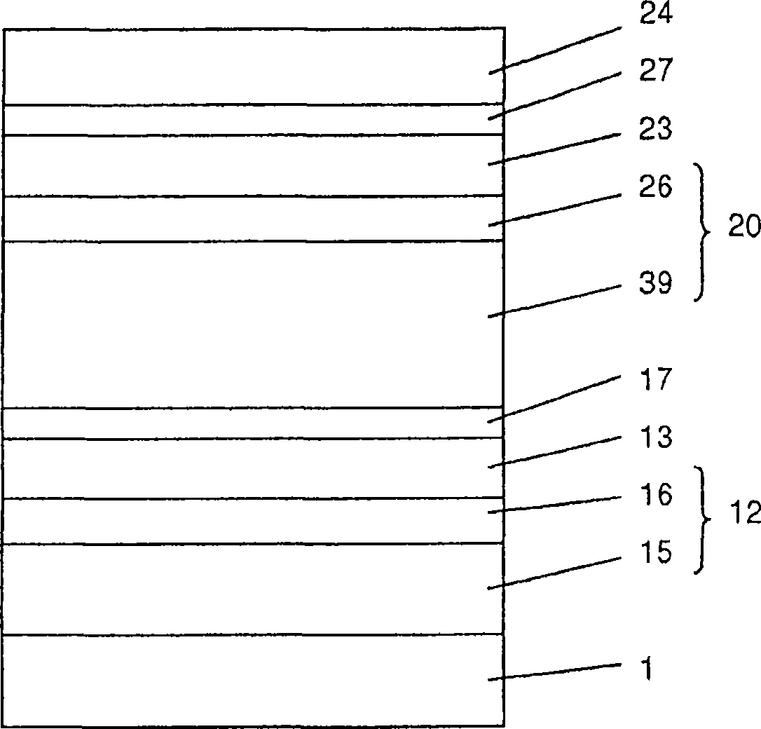
[0102] Coatings comprising the several layers indicated in Table 1 below were deposited onto glass plates in a sputtering apparatus with several separate sputtering chambers in which the following targets or pairs of targets were placed:

[0103] (1) The first target pair, including:

[0104] (a) metal-doped silicon target (in SISPA TM 10 commercially available from W.C. Heraeus), which contains about 10 wt.% of Al as the main dopant, and

[0105] (b) Ceramic aluminum-doped zinc oxide target (ZAO TM Commercially available from W.C. Heraeus), which contains about 2 wt.% Al 2 o 3 ;

[0106] (2) Zinc target;

[0107] (3) silver target;

[0108] (4) A second target pair, comprising

[0109] (a) Ceramic TiO x Target (xx CLATO TM Commercially available from W.C. Heraeus)

[0110] (b) Ceramic ZnO:Al target (ZAO TM Commercially available from W.C. Heraeus), which contains about 2 wt.% Al 2 o 3 .

[0111] The sputtering device allows moving the glass plate at a controlled...

Embodiment 2

[0121] A coating with essentially the same layer sequence and thickness as in Example 1 was deposited. However, the difference from Example 1 is that the compound layer is deposited by moving the substrate about 4 times faster under the Al-doped Si(Si:Al) / Al-doped ZnO(ZnO:Al) target pair , and by correspondingly employing 8-16-8 moves to deposit 3 compound layers having substantially the same total thickness as in Example 1. Table 3 summarizes the deposition conditions:

[0122] table 3

[0123] Attached picture

mark

target composition

the power

[kW] the power

Types of Ar

[sccm] N 2

[sccm] o 2

[sccm] speed

[mm / min] move

frequency

15

Si:Al /

ZnO:Al

10 / 2

Pulse DC

200

150

-

3284

8

16 Zn 14 DC 140 - 450 5900 1 13 Ag 1.5 DC 250 - - 1875 1

17

TiO x /

ZnO:Al

3 / 3

Pulse DC

...

Embodiment 4-9 and comparative example 10

[0139] In another series of experiments, the Si:Zn atomic ratio in the compound layer of a coating with a layer sequence similar to that of Example 1 was varied, with the following differences in addition:

[0140] - set the thicknesses of the compound layers 15, 39 and 24 in the coating of the invention and the (aluminum-doped) silicon nitride layer in the comparative coating of Comparative Example 10 to 40, 80 and 40 nm, respectively (as in Example 1 and 35, 70 and 35 nm in Comparative Example 3), a 2-4-2 movement was achieved under the target at a slightly reduced rate.

[0141] - The power ratio of the Si:Al / ZnO:Al target used to deposit the compound layers 15, 39 and 24 of a further embodiment of the invention was varied between 15:2 (Example 4) and 15:8 (Example 9) , thus achieving in these layers the Si:Zn atomic ratio shown in the second column of Table 5 below (from XPS analysis) (compared to about 2:1 in Examples 1 and 2).

[0142] All coated glass panels were heat ...


PUM

PropertyMeasurementUnit
thicknessaaaaaaaaaa
thicknessaaaaaaaaaa
thicknessaaaaaaaaaa

Abstract

The invention relates to a coated glass pane with a lower and/or solar control coating comprising at least one layer sequence which comprises at least the following transparent layers: a lower anti-reflection layer, an IR-reflecting layer, an upper anti-reflection layer. At least one of the anti-reflection layers comprises at least one compound layer containing a mixture of an (oxy)nitride of Si and/or Al and of ZnO. The inventive coated glass panes are preferably heat treatable, e.g. toughenable and/or bendable.

Description

technical field [0001] The present invention relates to coated glass panels with low-emissivity (low-e) and / or solar control coatings. Such visible light transparent coatings are well known in the art and generally comprise at least one infrared reflective layer embedded between a transparent lower dielectric antireflective layer and an upper dielectric antireflective layer. Background technique [0002] There is an increasing need for such heat treatable coated glass sheets. Many fields of application require heat-treated glass sheets which are tempered to impart safety properties and / or which are bent, eg for building or motor vehicle window panes. It is known that in order to thermally toughen and / or bend a glass sheet, it is necessary to treat the glass sheet by heat treating it at a temperature close to or above the softening point of the glass used and then either tempering the glass by rapid cooling or bending the glass by means of bending equipment. Glass. The rel...

Claims


Application Information

Patent Timeline
Patent Type & Authority Applications(China)
IPC IPC(8): C03C17/36
CPCC03C17/366C03C17/3694C03C17/36C03C17/3639C03C17/3618C03C17/3644C03C17/3626Y10T428/265C03C17/06C03C17/22
Inventor G·加格里亚蒂D·A·伍德J·R·赛德尔M·朗希
Owner PILKINGTON GROUP LTD
Why Eureka
Try Eureka