

Ground-dipping ore bed continuous high-energy gas fracturing seepage increasing method and specific high-energy gas generator
A high-energy gas fracturing and high-energy gas technology, which is applied in the field of improving the permeability of ore-hosting rock formations, can solve the problems that are not conducive to the full reaction of the leaching solution and uranium minerals, the permeability of the ore layer is not conducive to in-situ leaching mining, and cannot be leached by leaching agents. Ore and other issues, to achieve the effect of improving recovery rate and unit yield, improving utilization efficiency and increasing permeability
- Summary
- Abstract
- Description
- Claims
- Application Information
AI Technical Summary
Problems solved by technology
Method used
Image

Examples
Embodiment 1
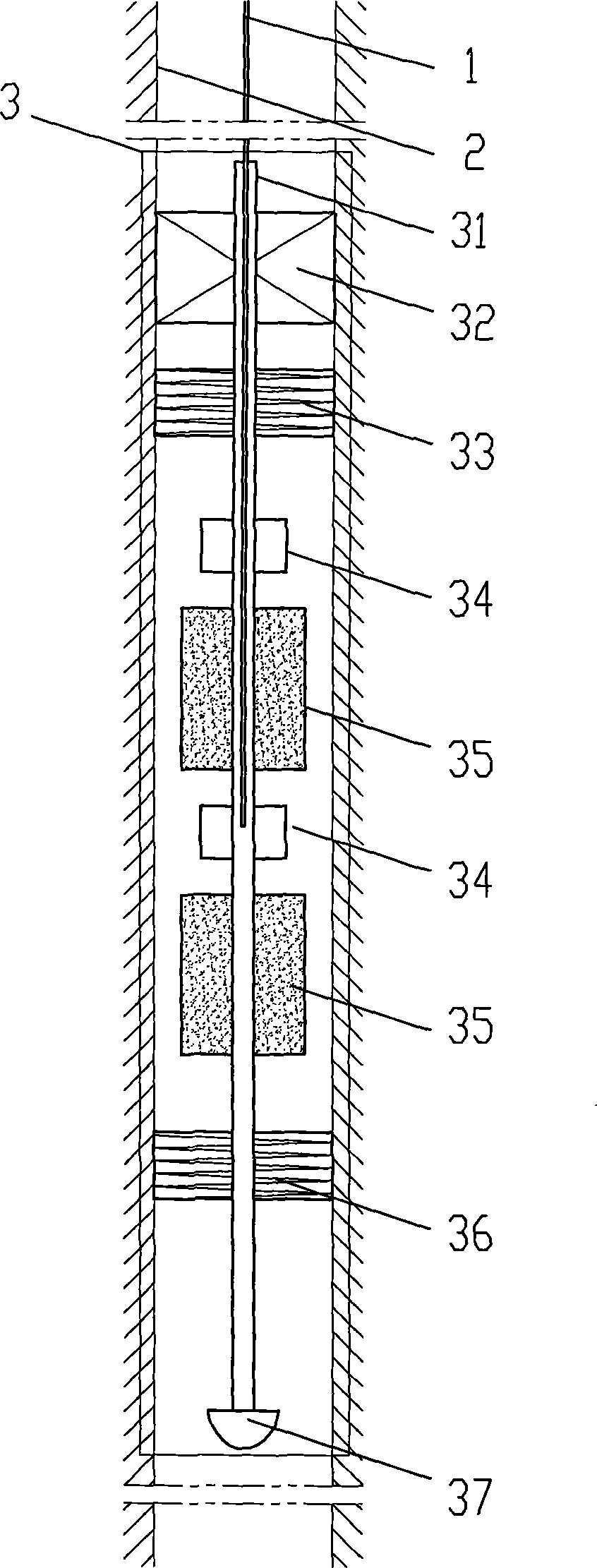
[0032] In-situ leachable sandstone permeability is 10 -6 D, the compressive strength of sandstone is 200MPa, and the implementation process of the continuous high-energy gas fracturing method for increasing permeability is as follows: through the production well 2, the high-energy gas generator 3 is sent to the ore-hosting rock layer with the cable 1, and is tightly combined with the production well through the plugging device 32 The high-energy gas generator 3 is fixed, and the deflagration bomb 35 is ignited by a delay igniter 34 . The high-energy gas generator 3 is connected in series with 10 deflagration bombs 35 and 10 delay igniters 34. The first deflagration bomb is solid explosive, and the remaining 9 deflagration bombs are solid explosives. The delay time of the delay igniter 34 For 1 minute, control the peak pressure of the high-energy gas in the production well to 500MPa. After the high-energy gas acts on the ore layer for 30 minutes, close the plugging device and r...
Embodiment 2
[0034] In-situ leachable sandstone permeability is 10 -4 D, the compressive strength of the sandstone is 160MPa, and the implementation process of the high-energy gas fracturing method for increasing permeability is as follows: the high-energy gas generator 3 is sent to the ore-hosting rock formation through the production well 2 with the cable 1, and is tightly combined with the production well through the plugging device 32 The high-energy gas generator 3 is fixed, and the deflagration bomb 35 is ignited by a delay igniter 34 . The high-energy gas generator 3 is connected in series with 6 deflagration bombs 35 and 6 delay igniters 34, the first deflagration bomb is solid explosive, the remaining 5 deflagration bombs are solid powder, and the delay time of the delay igniter 34 For 40 seconds, control the peak pressure of the high-energy gas in the production well to 400MPa. After the high-energy gas acts on the ore layer for 25 minutes, close the plugging device and relieve t...
Embodiment 3
[0036] In-situ leachable sandstone permeability is 10 -3D, the compressive strength of sandstone is 130MPa, and the implementation process of the high-energy gas fracturing method for increasing permeability is as follows: through the production well 2, the high-energy gas generator 3 is sent to the ore-hosting rock formation with the cable 1, and is tightly combined with the production well through the plugging device 32 The high-energy gas generator 3 is fixed, and the deflagration bomb 35 is ignited by a delay igniter 34 . The high-energy gas generator 3 is connected in series with 4 deflagration bombs 35 and 4 delay igniters 34. The four deflagration bombs contain liquid gunpowder, and the delay time of the delay igniter 34 is 20 seconds to control the peak pressure of the high-energy gas in the production well. The size is 300MPa. After the high-energy gas acts on the mine layer for 20 minutes, close the plugging device and relieve the pressure on the mine layer, so that ...
PUM
 Abstract
Description
Claims
Application Information