Multiple-domain vertical orientating type liquid crystal display device and its manufacture method

A liquid crystal display device and vertical alignment technology, which is applied in semiconductor/solid-state device manufacturing, optics, instruments, etc., can solve the problems of rising manufacturing costs, reducing pixel aperture ratio, and reducing the light-transmitting part of the pixel area, so as not to affect The effect of aperture ratio

Active Publication Date: 2009-05-27
NANJING CEC PANDA LCD TECH
View PDF1 Cites 16 Cited by
  • Summary
  • Abstract
  • Description
  • Claims
  • Application Information

AI Technical Summary

Problems solved by technology

However, the current capacitive coupling technology usually forms the capacitive coupling layer while forming the second conductive metal, so the capacitive coupling layer is an opaque metal, which reduces the light-transmitting part of the pixel area, thereby reducing the aperture ratio of the pixel. , which leads to an increase in manufacturing cost

Method used


Image

  • Multiple-domain vertical orientating type liquid crystal display device and its manufacture method
  • Multiple-domain vertical orientating type liquid crystal display device and its manufacture method
  • Multiple-domain vertical orientating type liquid crystal display device and its manufacture method

Examples


Embodiment 1

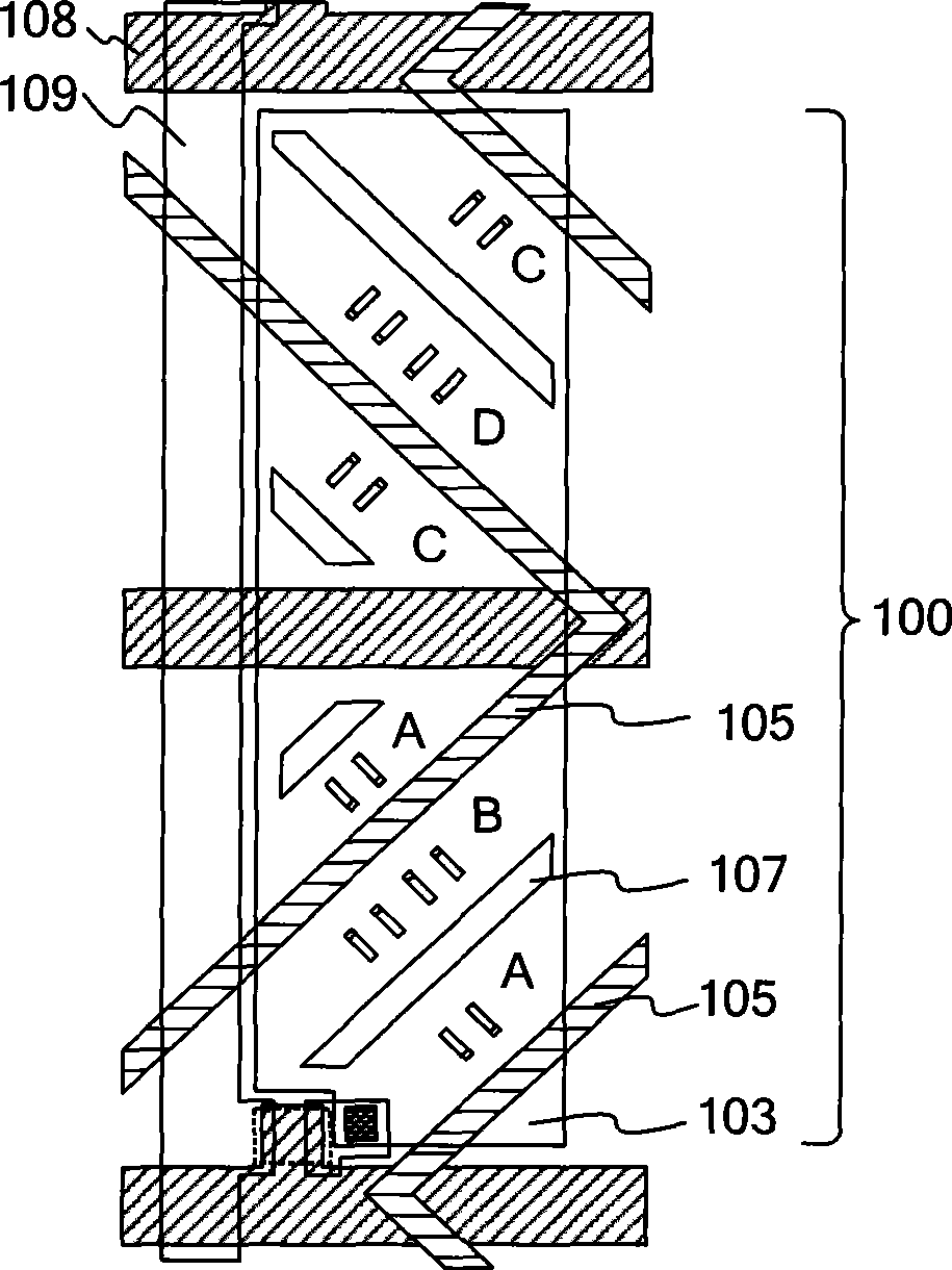
[0048] Figure 4A is a top view of the array substrate of the present invention, Figure 4B for along Figure 4A A cross-sectional view in the direction of A-A'.

[0049] See Figure 4A , the liquid crystal display device of the present invention includes: a first substrate (also known as an array substrate, not shown in the figure) and a second substrate (also known as a color filter substrate, not shown in the figure); Liquid crystal layer (not shown); scanning electrode lines 401 and signal electrode lines 406 intersecting each other on the first substrate and defining sub-pixel areas; controlled by scanning electrode lines 401 to open a thin film transistor switch 407, and signal electrode lines 406 pass through The switch charges the first pixel electrode 402; a second pixel electrode 405 is formed on the first substrate at the same time, and this electrode is not directly connected to the first pixel electrode 402 electrically, and is not connected to the thin film tr...

Embodiment 2

[0052] Figure 5 is a cross-sectional view of the array substrate in the second embodiment of the present invention.

[0053] See Figure 5 After the gate electrode, the gate insulating layer 408, the semiconductor layer, the drain / source electrode, and the passivation layer 410 are sequentially formed on the transparent substrate 408 in this embodiment, a layer of transparent electrode is made first, and a pattern is engraved as the first Pixel electrode 402; then apply insulating film 411, etch the insulating film 411 above the first pixel electrode 402 in the non-coupling region to expose the first pixel electrode 402; make a layer of transparent electrode, and carve a pattern as the second Pixel electrode 405 . The advantage of this method is that there is one less insulating film above the first pixel electrode 402, which improves the light transmittance.

Embodiment 3

[0055] Image 6 It is the production flowchart of the third embodiment of the present invention.

[0056] See Image 6 , this embodiment is a further improvement on the second embodiment. After the gate, gate insulating layer 408, semiconductor layer, drain / source, and passivation layer 410 are sequentially formed on the transparent substrate 408, a layer of transparent electrode is made first, and a pattern is carved as the first pixel electrode 402; then Coating the insulating film 411, and then making the second transparent electrode layer, etching out the pattern as the second pixel electrode 405 through the dry etching process; and then etching the insulating film 411 not covered by the second pixel electrode 405 through the wet etching process , exposing the first pixel electrode 402 . The advantage of this method is that it can save a photolithography process and reduce the cost.


PUM


Abstract

The invention relates to a multi-domain vertical orientation type liquid crystal display device and a manufacturing method thereof. The liquid crystal display device comprises a first basal plate and a second basal plate which are arranged oppositely, a liquid crystal layer which is filled between the first basal plate and the second basal plate, a pixel electrode which is formed on the first basal plate, and a common transparent electrode which is formed on the second basal plate, wherein the pixel electrode comprises a first pixel electrode and a second pixel electrode which are partially laminated and are electrically insulated from each other, and an insulation film is arranged between the first pixel electrode and the second pixel electrode. The multi-domain vertical orientation type liquid crystal display device and the manufacturing method thereof can realize multi-domain display through capacitance coupling without impacting the opening rate.

Description

technical field [0001] The invention relates to a display device and a manufacturing method thereof, in particular to a multi-domain vertical alignment type (Multi-domain Vertical Alignment) liquid crystal display device and a manufacturing method thereof. Background technique [0002] With the development of liquid crystal flat panel display technology, large-size liquid crystal display devices are more and more widely used. High-end liquid crystal displays are developing in the direction of high contrast, wide viewing angle, fast dynamic response, and wide color gamut. [0003] Currently, there are two widely used wide viewing angle display modes: Multi-domain Vertical Alignment (MVA) and In Plane Switch (IPS). In vertically aligned liquid crystal displays, negative liquid crystals are used to form liquid crystal cells. Referring to US invention 6661488B1, as Figure 1A As shown, when no voltage is applied to the first substrate 101 and the second substrate 104 of the li...

Claims


Application Information

Patent Timeline
Patent Type & Authority Applications(China)
IPC IPC(8): G02F1/1362G02F1/1343H01L27/12H01L21/84
Inventor 陆海峰陈钢
Owner NANJING CEC PANDA LCD TECH
Why Eureka
Try Eureka