
Front and rear automatic shear line device of overedger sewing products

A technology for sewing products and overlock sewing machines, applied in the field of automatic devices, can solve problems such as low efficiency, low efficiency, lubricant pollution, etc., and achieve the effects of high efficiency, improved work efficiency, and high reliability

Inactive Publication Date: 2009-06-03
王国秋 +1
View PDF0 Cites 20 Cited by
  • Summary
  • Abstract
  • Description
  • Claims
  • Application Information

AI Technical Summary

Problems solved by technology

[0002] At present, various types of overlock sewing machines do not have an automatic thread cutting device, and thread cutting has become a cumbersome process in garment factories. Due to the requirements of the production process, the length of the overlock thread required to produce different products needs to be controlled. Line workers, or sewing workers stop the machine with scissors and cut the thread; labor costs are high and efficiency is low; factories are constantly adding new equipment to increase production capacity in order to improve efficiency; these measures will undoubtedly increase the manufacturing cost of the factory
[0003] In order to solve these problems, some thread trimming devices are also added, and the trimming of the tail of the sewing product is completed by manually pressing the switch after parking the car. Although this method can trim the thread, it needs to be manually judged by visual inspection after parking. Cut position to complete the action, not efficient and just cut the thread at the end of the sewing product
[0004] Use the locomotive rotation stroke to determine the position of the sewing product to complete the thread trimming process. Due to the use of the direct reflection electric eye outside the presser foot, due to the non-standard operation of the sewing worker, it is easy to fail to accurately locate the starting position of the sewing product, and often It can cut the sewn products into waste products. This technology also cannot cut the thread wool at the front end of the sewn products. At the same time, the cost of this device is expensive, and the general factory cannot add it.
[0005] Using the linkage mechanism, it is not easy to install the existing equipment, there are many parts, the continuous operation is not smooth, and the lubricant is polluted, which affects the product quality. It is impossible to accurately cut the front end and the rear end of the sewing product thread, which is not conducive to general application.
[0006] Because the overlock sewing machine needs to cut the thread in a small space, the existing technical devices have not been able to completely solve the factory's need to complete high-efficiency, low-cost and reliable front and rear cutting threads.

Method used


Image

  • Front and rear automatic shear line device of overedger sewing products
  • Front and rear automatic shear line device of overedger sewing products
  • Front and rear automatic shear line device of overedger sewing products

Examples


Embodiment

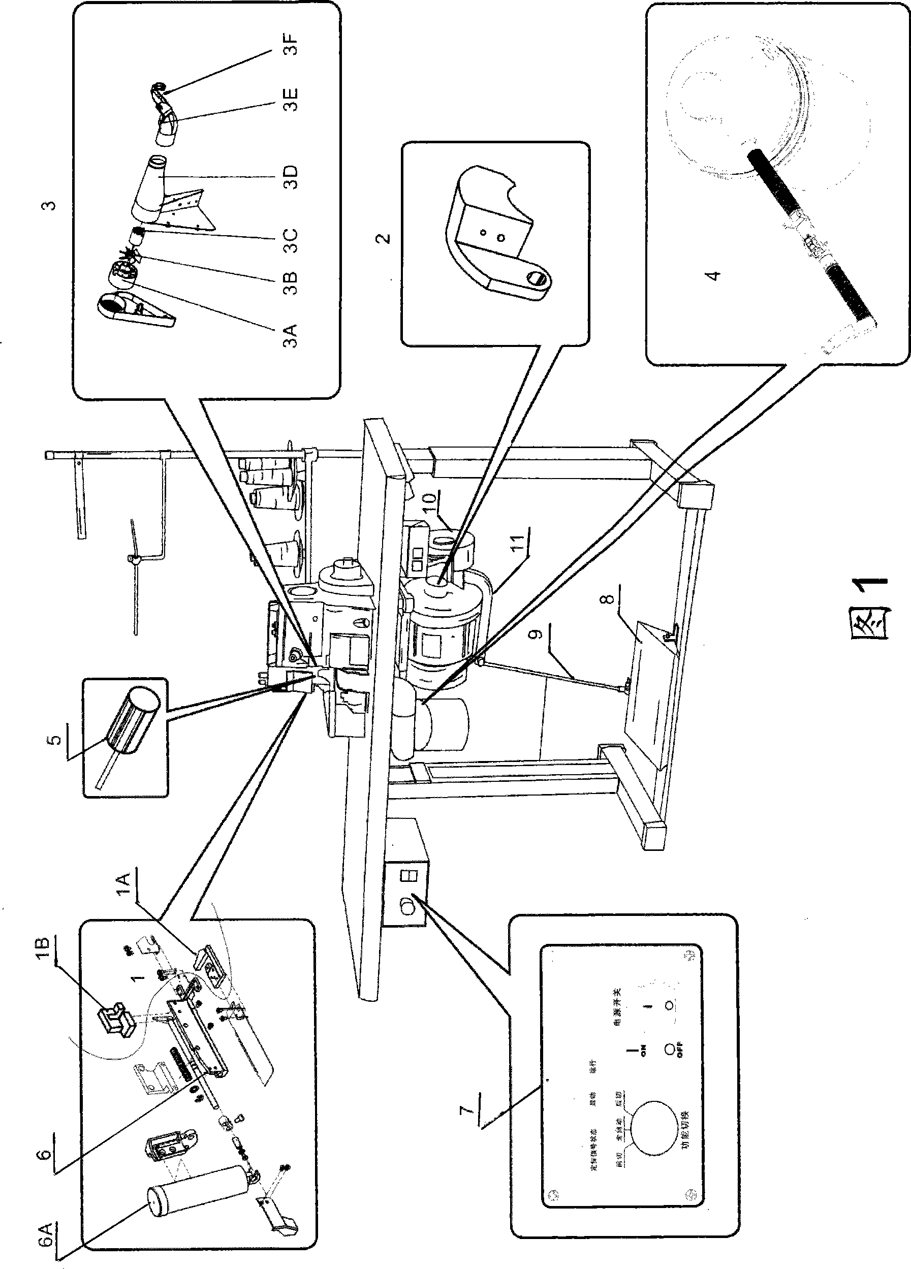
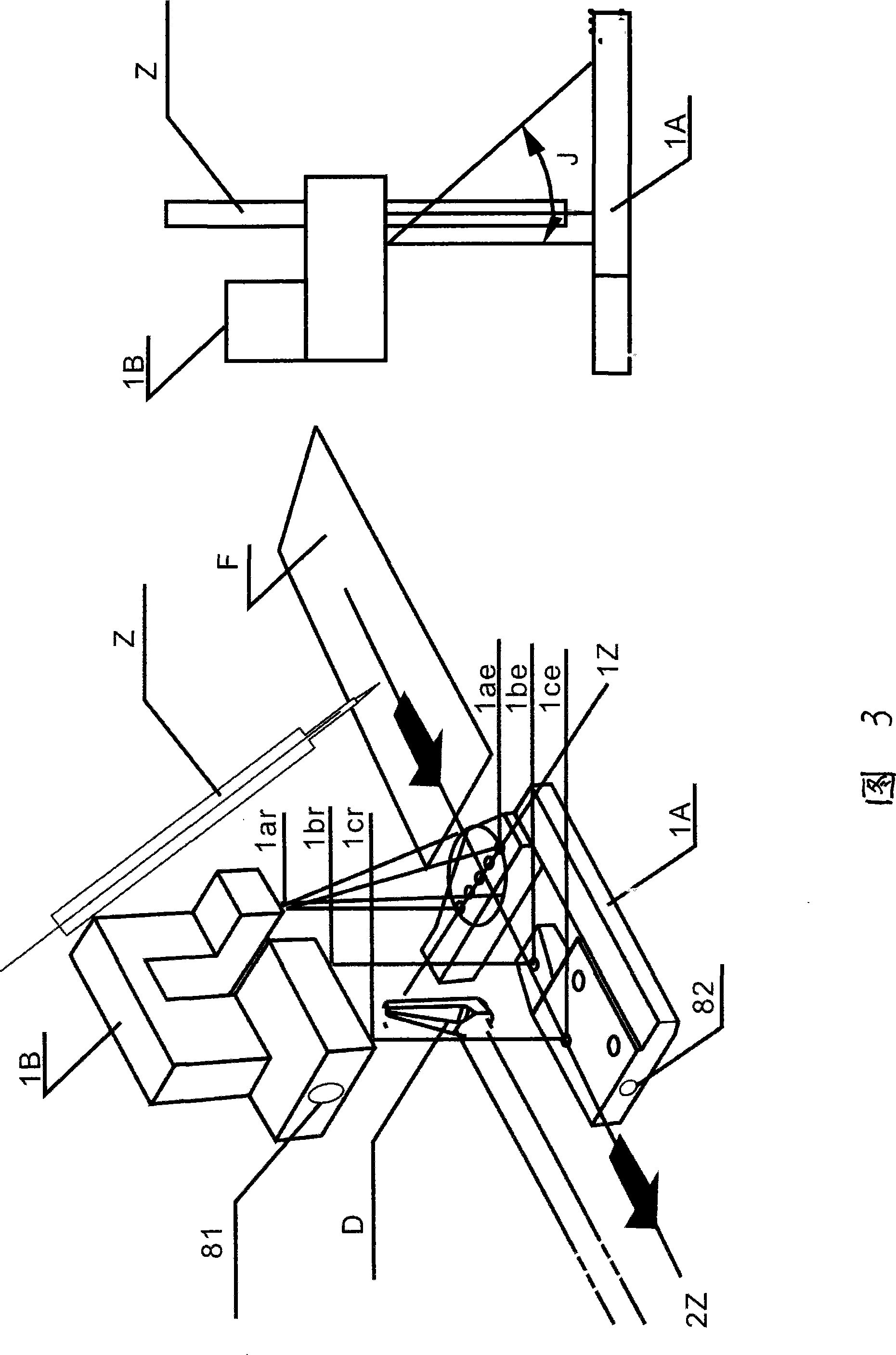
[0063] Figure 1, Figure 3, Figure 4 As shown in , the transmissive synchronous scanning photoelectric group 1 is composed of more than two transmitters and more than two receivers. It is installed on the electromagnetic or pneumatic shearing knife frame 6, and the synchronous scanning photoelectric group emission group 1A is installed on the pin Z In front of the presser foot Y, the sewing product F moves in parallel above it, the first emitting light source 1ae of the synchronous scanning photoelectric group emitting group 1A is opposite to the first receiver 1ar of the synchronous scanning photoelectric group receiving group 1B, and the first The first receiver 1br forms a receiving closed optical path with a conical angle J not greater than 90 degrees in front, back, left, and right on the axis 1Z of the first emitting light source 1ae, and the stitched product F is connected with the first emitting light source 1ae and the first receiver 1ar A closed optical path is forme...


PUM


Abstract

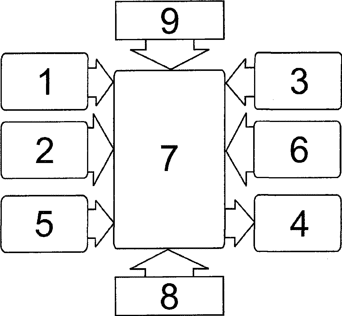
The invention discloses a front and rear automatic shear line device of overedger sewing products, which consists of a transmission-type synchronous scanning opto-electronic group, a blowing device, an enabling signal sensor, a front cut dust collecting device, a stepping sensor, an electromagnetic or pneumatic shear knife rest (an executing mechanism) and an electrical control box. A full-automatic shear line device which is provided with a front blade and a rear blade of the sewing products that are controlled by photoelectric detection; on the premise of no human intervention, the shear process of freely setting yarn at the front end and the rear end of the sewing products can be completed. As the device is not needed to be stopped for trimming, the sheared thrum is absorbed cleanly at the same time. As the device is not needed to be stopped for trimming, and the sheared thrum is absorbed cleanly at the same time, the working efficiency of the single device is increased by over 30% compared with the prior art; the efficiency and the reliability are high.

Description

technical field [0001] The invention relates to the field of sewing equipment, in particular to an automatic device used for overlock sewing machines to cut sewing threads back and forth on sewing products. Background technique [0002] At present, various types of overlock sewing machines do not have an automatic thread cutting device, and thread cutting has become a cumbersome process in garment factories. Due to the requirements of the production process, the length of the overlock thread required to produce different products needs to be controlled. Line workers, or sewing workers use scissors to stop and cut the thread; labor costs are high and efficiency is low; factories are constantly adding new equipment to increase production capacity in order to improve efficiency; these measures will undoubtedly increase the manufacturing cost of the factory. [0003] In order to solve these problems, some thread trimming devices are also added, and the trimming of the tail of th...

Claims


Application Information

Patent Timeline
IPC IPC(8): D05B65/00D05B69/00
Inventor 王国秋钱雄峰陈志向
Owner 王国秋
Learn More