Pneumatic brake motor and pneumatic brake method
A pneumatic brake and electric motor technology, which is applied in the direction of brake actuators, electric components, and mechanical energy control, can solve the problems of high assembly accuracy, large rectifier power consumption, rectifier burnout, etc., and achieve low assembly accuracy requirements and manufacturing Low cost and adjustable braking force
- Summary
- Abstract
- Description
- Claims
- Application Information
AI Technical Summary
Problems solved by technology
Method used
Image
Examples
Embodiment 1
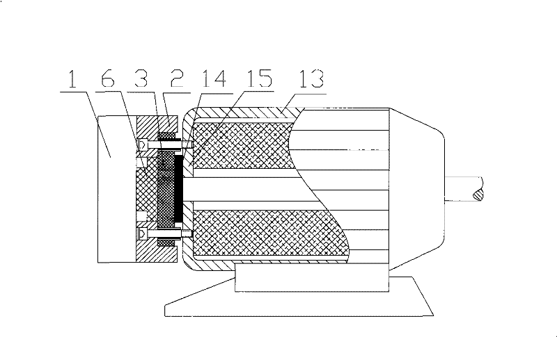
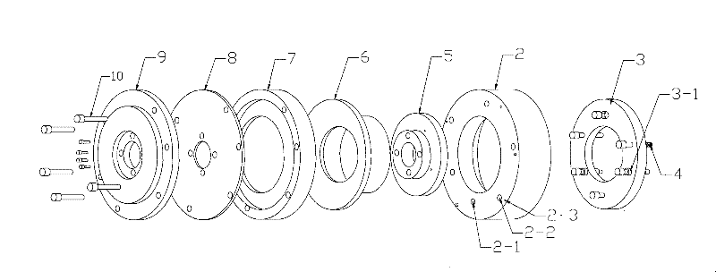
[0010] Example 1: Refer to the attached figure 1 with 2 . Pneumatic brake motor, the brake pad 3 is located in the groove on one side of the base 2 and the braking surface of the brake pad 3 and the friction pad 14 in the motor 13 form a brake and brake cooperation. The end surface of the base 2 and the end surface 15 of the motor 13 Connected, the other side of the base 2 is connected with the brake cylinder 1 and the piston 6 in the brake cylinder 1 pushes the brake pad 3 to brake. There are 3 or more base countersunk bolt holes on the brake pad 3. The movable sliding sleeve 3-1 is located in the hole of the brake pad 3 and uses the connecting screw of the base 2 and the motor as the sliding column and the brake pad 3. Sliding fit; the base 2 is equipped with 3 or more return spring positioning bolts 2-1 and corresponds to the 3 or more through holes on the brake pad 3. The bolts of 3 or more bolts pass through the brake The through hole of the plate 3, the bolt rod is cover...
Embodiment 2
[0011] Example 2: On the basis of Example 1, the brake cylinder 1 is composed of a film cylinder base 9, a film 8, an outer ring flange 7, a piston 6, an inner ring flange 5, a brake pad 3, and a side end surface of the base 2. The film 8 is located in the cavity formed by the base 9 of the film cylinder, the outer ring flange 7, and the inner ring flange 5. The piston 6 is located between the outer ring flange 7 and the inner ring flange 5. The ring flange 7, the film 8 and the film cylinder base 9 form a hollow shaft film cylinder by bolts 10 and 11. At the same time, it is fixed on the base 2 with bolts 10 to form a whole with the base 2. The film cylinder base 9 and the film 8 An annular sealed cavity is formed between the film cylinder base 9 and an air inlet 12 is provided on the base 9 of the film cylinder and communicates with an air outlet of compressed air.
Embodiment 3
[0012] Embodiment 3: On the basis of Embodiment 1, the brake cylinder 1 can be an electric cylinder. The structure of the electric cylinder is based on the prior art and will not be described here.
PUM
 Abstract
Description
Claims
Application Information
 - R&D
- Intellectual Property
- Life Sciences
- Materials
- Tech Scout
- Unparalleled Data Quality
- Higher Quality Content
- 60% Fewer Hallucinations
Browse by: Latest US Patents, China's latest patents, Technical Efficacy Thesaurus, Application Domain, Technology Topic, Popular Technical Reports.
© 2025 PatSnap. All rights reserved.Legal|Privacy policy|Modern Slavery Act Transparency Statement|Sitemap|About US| Contact US: help@patsnap.com


