
Spiral trumpet shaped microwave energy reclaiming antenna and array microwave heating apparatus thereof

A technology of energy-feeding antenna and horn antenna, which is applied in the field of industrial microwave heating, can solve the problems of shortening the working life of magnetron, single mode, and poor effect, so as to reduce the mutual coupling phenomenon of electromagnetic waves at ports, improve life and reliability, The effect of reducing equipment maintenance costs

Inactive Publication Date: 2011-06-15
UNIV OF ELECTRONICS SCI & TECH OF CHINA
View PDF0 Cites 0 Cited by
  • Summary
  • Abstract
  • Description
  • Claims
  • Application Information

AI Technical Summary

Problems solved by technology

Due to the large number of tubes (a few, dozens, hundreds or even thousands) and a single mode, electromagnetic mutual coupling is easily generated near each radiation port, resulting in a decrease in the output power of each adjacent magnetron, coupling The efficiency is reduced, and in severe cases, the magnetron will be damaged; on the other hand, the moisture and other volatiles discharged from the material during the heating process can only be ventilated and dehumidified from the side openings, which is not efficient and the effect is not good. Once pollutants such as gas enter the energy feeding port of the top magnetron, it is very easy to cause problems such as sparking outside or inside the tube, mode jumping, etc., shortening the working life of the magnetron, and even damaging the power supply.

Method used


Image

  • Spiral trumpet shaped microwave energy reclaiming antenna and array microwave heating apparatus thereof
  • Spiral trumpet shaped microwave energy reclaiming antenna and array microwave heating apparatus thereof
  • Spiral trumpet shaped microwave energy reclaiming antenna and array microwave heating apparatus thereof

Examples


Embodiment Construction

[0018] Below in conjunction with accompanying drawing and embodiment example, the present invention will be further described

[0019] The specific parameters and dimensions of each part of this implementation case are as follows:

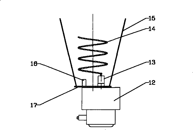
[0020] This implementation case is designed according to the operating frequency of the microwave source is 2450MHz, the helical horn antenna (see figure 2 The shell in ) is made of aluminum or stainless steel, the radius of the horn antenna base plate 17 is 42mm, the horn mouth radius at the top of the tapered horn cylinder body 15 is 80mm, and the height of the cone horn cylinder 15 is 170mm; the spiral radius of the helical antenna 14 is 32mm, The helical wire radius of the helical antenna 14 is 2 mm, the pitch is 40 mm, and the number of turns is 3.5; the diameter of the magnetron output antenna head 13 is 17 mm, the height from the bottom plate is 6 mm, and the distance from the center to the horn axis is 21 mm; the radius of the matching pin...


PUM


Abstract

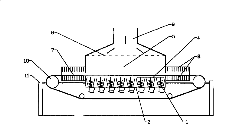
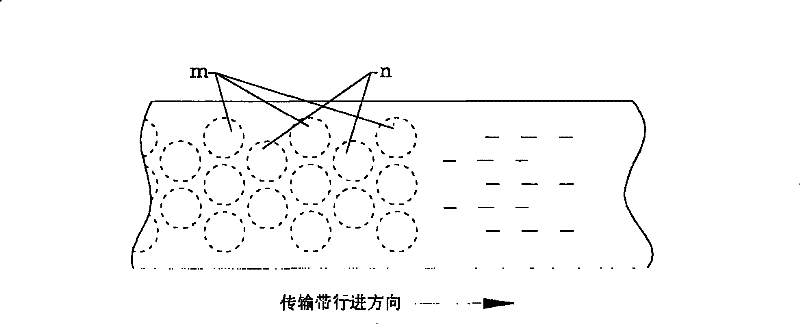
The invention discloses a spiral trumpet shaped microwave energy reclaiming antenna and an array microwave heating apparatus thereof, and relates to microwave heating technology in microwave energy application technology. In the energy reclaiming antenna, a conical trumpet cylinder (15) is eccentrically arranged on a magnetron (12) through a trumpet antenna soleplate (17); and a spiral antenna (14) is arranged on an output antenna head (13) of the magnetron (12). In the microwave heating apparatus of the spiral trumpet shaped microwave energy reclaiming antenna array, the microwave energy reclaiming antenna array is formed by arranging a plurality of spiral trumpet shaped microwave energy reclaiming antennas (1) in delta staggered mode, and radiation ports of all the spiral trumpet shapedmicrowave energy reclaiming antennas (1) are upward. The spiral trumpet shaped microwave energy reclaiming antenna improves microwave power output efficiency; and the microwave heating apparatus of the spiral trumpet shaped microwave energy reclaiming antenna array has the advantages of higher microwave power output efficiency and coupling efficiency, even heating and smooth moisture discharge, improves working reliability and service life of the magnetron, and saves production and maintenance cost of equipment.

Description

technical field [0001] The invention belongs to the technical field of microwave energy application and relates to industrial microwave heating technology. Background technique [0002] In the field of microwave energy application technology, two main frequency bands recommended by the International Microwave Energy Institute (IMPI), namely 915MHz and 2450MHz frequency bands, are widely used. For decades, people have created and produced many box-type or tunnel-type microwave heating applications for material heating, heating, dehydration, drying, sterilization, whitening, puffing, synthesis, extraction, vulcanization, desulfurization, etc. , in order to meet the different needs of furnace-by-furnace intermittent production and continuous production. In the continuous production of various tunnel-type multi-mode cavity applications, it is divided into two structures: high-power single-tube energy-feeding type and a large number of low-power magnetron distributed energy-feed...

Claims


Application Information

Patent Timeline
Patent Type & Authority Patents(China)
IPC IPC(8): H05B6/72H05B6/64H05B6/78F24C7/02
CPCH05B6/78H05B6/701H05B6/72H05B6/76
Inventor 张兆镗黎晓云李承跃
Owner UNIV OF ELECTRONICS SCI & TECH OF CHINA
Learn More