Interdental brush

A toothbrush and interdental technology, which is applied in the direction of brushes, brush bodies, bristles, etc., can solve the problems of no buffer function, etc., and achieve the effect of improving the buffering effect, saving materials, and reducing the risk of damage or pain

Active Publication Date: 2009-06-03
TEPE MUNHYGIENPRODUKTER AB
View PDF10 Cites 5 Cited by
  • Summary
  • Abstract
  • Description
  • Claims
  • Application Information

AI Technical Summary

Problems solved by technology

The interdental toothbrushes disclosed in these two documents have no cushioning function at all

Method used


Image

  • Interdental brush
  • Interdental brush
  • Interdental brush

Examples


Embodiment Construction

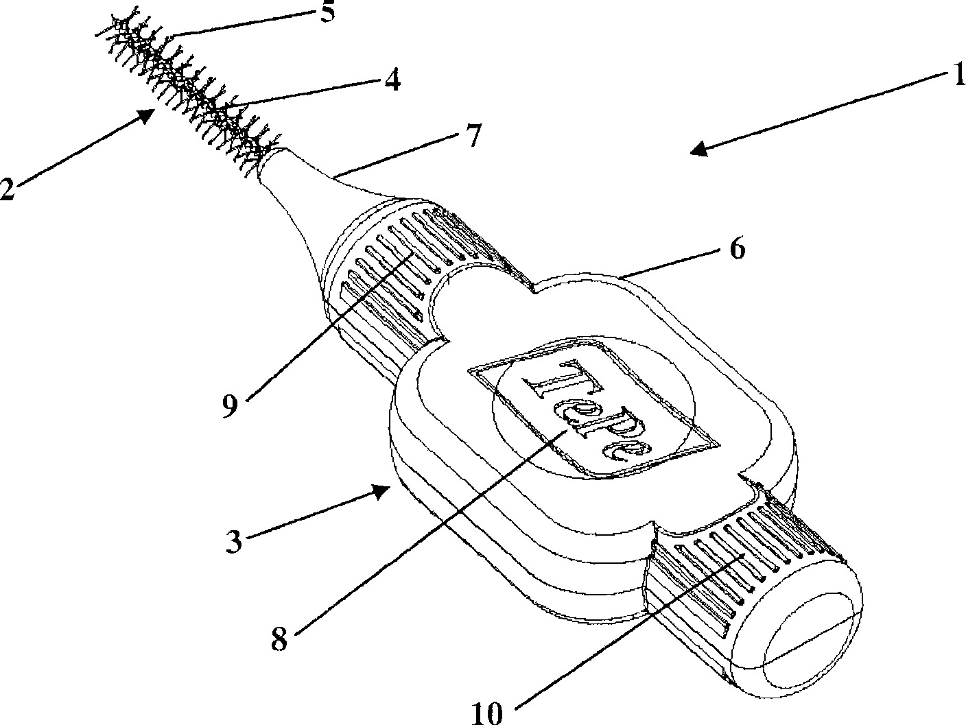
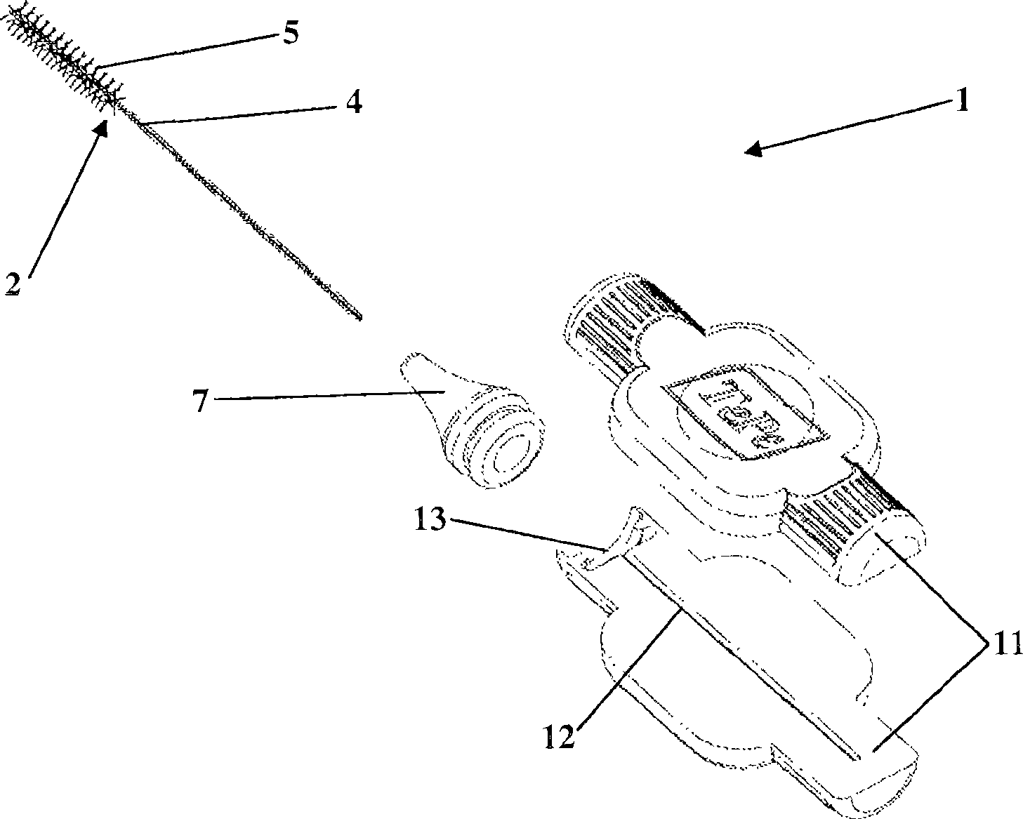
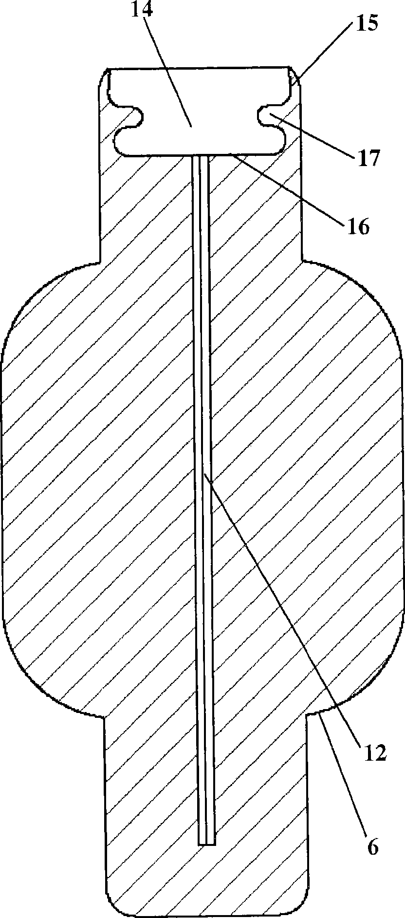
[0028] Referring to the attached drawings, first of all Figure 1 to Figure 4 , a preferred embodiment of the interdental toothbrush of the present invention is marked 1 . The interdental toothbrush comprises a brush part 2 and a handle part 3 .

[0029]The brush part 2 of the interdental toothbrush 1 comprises a spine 4 and a plurality of bristle filaments 5 secured to the ends of the spine 4 . With regard to the choice of material and the means for securing the bristle filaments 5 to the spine 4, various options are possible. In a preferred embodiment, the spine 4 is made of a metal wire covered with plastic, which is crimped to cooperate with the bristle filaments 5 made of polyamide. Crimping as known in the art involves folding a length of thread into a spine 4 with two legs, placing the bristle filament 5 between the two legs along the length of the end of the spine 4, and crimping the spine 4 , thus the bristle filaments 5 are fixed between the legs of the spine 4 . ...


PUM


Abstract

An interdental brush comprises a brush member (2) having bristle filaments (5) attached to a spine (4) which projects from a handle part (3). The handle part (3) comprises a main body and a resilient transition portion (7). The handle part (3) further comprises a hollow cavity (20), in the transition portion (7). The hollow cavity (20) improves the cushioning effect of the transition portion (7),and increases the length of stroke of the interdental brush by allowing the transition portion (7) to be deformed.

Description

technical field [0001] This invention relates to the field of oral hygiene and instruments therefor, and more particularly, to interdental toothbrushes. Interdental toothbrushes are used by dentists and dental hygienists in the clinic, and by consumers at home. Interdental toothbrushes are designed to clean the area between your teeth, that is, the area between two adjacent teeth. Keeping the area between teeth clean by removing biofilm (ie plaque and deposits) reduces the risk of dental caries and gum disease and often has a beneficial effect on the user's oral hygiene. Background technique [0002] Interdental toothbrushes have been in use for quite some time. One of the earlier documents in the prior art is US-A-4691404, which discloses an interdental toothbrush comprising a brush portion having bristles secured to spines of crimped metal wires. The ridge is embedded in a handle made of a mixture of thermoplastic elastomer and polypropylene material. The brush portion...

Claims


Application Information

Patent Timeline
Patent Type & Authority Applications(China)
IPC IPC(8): A46B9/04A46B5/00
Inventor J·拉松B·萨雷P·瓦尔斯特伦
Owner TEPE MUNHYGIENPRODUKTER AB
Why Eureka
Try Eureka