Electromotor diver and compressor diver

A driving device and motor technology, which is applied in the control of electromechanical transmission devices, motor generator control, AC motor control, etc., can solve the problems of reducing input current, narrowing the operating range, etc., and achieve the effect of reducing high-order harmonic components

Active Publication Date: 2009-06-03
MITSUBISHI ELECTRIC CORP
View PDF8 Cites 29 Cited by
  • Summary
  • Abstract
  • Description
  • Claims
  • Application Information

AI Technical Summary

Problems solved by technology

[0022] However, these motor drive devices need to narrow the operating range to a variable speed range that can drive the motor and reduce the harmonic current of the input current
[00

Method used


Image

  • Electromotor diver and compressor diver
  • Electromotor diver and compressor diver
  • Electromotor diver and compressor diver

Examples


Embodiment approach 1

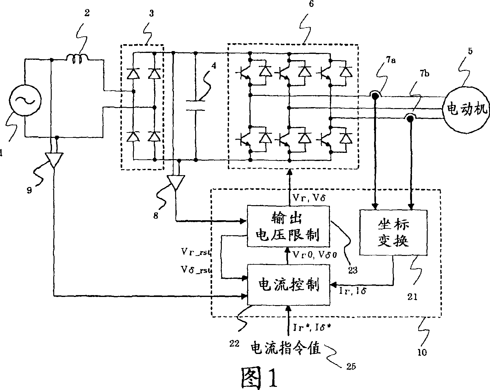
[0057] FIG. 1 is a block circuit diagram of a motor drive device according to Embodiment 1 of the present invention.

[0058] In Fig. 1, 1 is a single-phase AC power supply, 2 is a coil, 3 is a rectifier unit, 4 is a smoothing capacitor, 5 is a motor, 6 is an inverter main circuit section, 7a and 7b are phase current detectors, and 8 is a DC voltage detection unit, 9 is a power phase detector, 10 is a control unit.

[0059] The coil 2 is connected between the single-phase AC power source 1 and the rectification unit 3 .

[0060]The rectifying unit 3 rectifies the AC voltage from the single-phase AC power supply 1 into a DC voltage.

[0061] The smoothing capacitor 4 is connected to the output side of the rectification unit 3 to smooth the voltage rectified by the rectification unit 3 .

[0062] The motor 5 is connected to the output side of the inverter main circuit unit 6 and becomes a drive target of the motor drive device according to the first embodiment.

[0063] The i...

Embodiment approach 2

[0165] Figure 7 It is a circuit block diagram of the motor drive device according to Embodiment 2 of the present invention.

[0166] exist Figure 7 Among them, the control unit 10 has a current command generation unit 26 .

[0167] The current command generating unit 26 receives the speed command, the magnetic flux command, the output of the coordinate conversion unit 21, the output of the output voltage limiting unit 23, and the output of the power supply phase detector 9, and outputs a current command value 25 (Ir * , Iδ * ).

[0168] The other configurations are the same as those in Embodiment 1, so the same symbols are assigned and descriptions thereof are omitted.

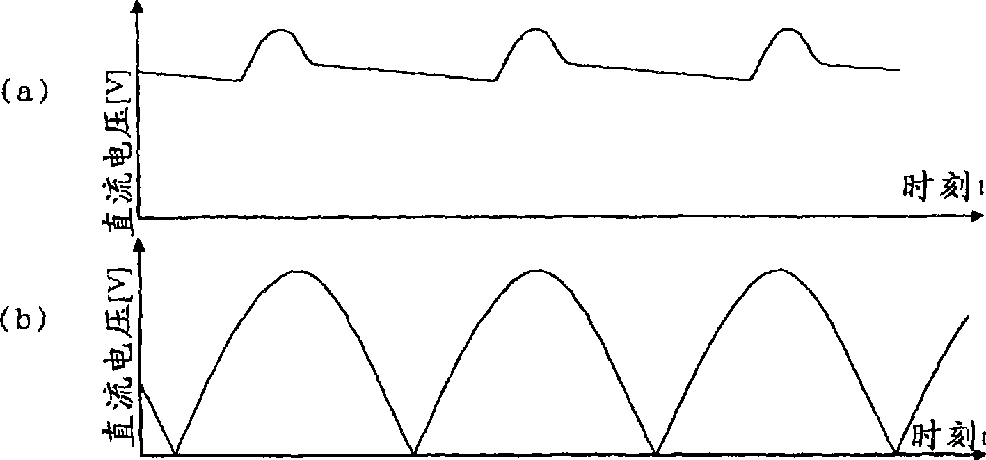
[0169] Also in the second embodiment, as in the first embodiment, since the DC voltage applied to the inverter main circuit unit 6 drops due to ripples, it is sometimes necessary to limit the voltage applied to the motor 5 .

[0170] As a technique corresponding to this situation, there is a technique o...

Embodiment approach 3

[0256] Figure 14 It is a circuit block diagram of a motor drive device according to Embodiment 3 of the present invention.

[0257] exist Figure 14 Among them, the control unit 10 has a position estimation unit 27 .

[0258] The position estimating unit 27 receives the output of the coordinate conversion unit 21 and the output of the output voltage limiting unit 23 , and estimates the energization phase and the rotational speed of the motor 5 .

[0259] The other configurations are the same as those in Embodiment 2, so the same symbols are used to omit description.

[0260] Here, a general problem in estimating the energization phase and the rotational speed of the electric motor 5 will be described first, and then the specific operation of the position estimating means 27 in the third embodiment will be described.

[0261] For example, when the electric motor 5 is a permanent magnet motor, during variable speed operation, the torque is controlled by passing current throu...


PUM


Abstract

This invention claims an electromotor driver and compressor driver loading the motor driver. The motor driver makes the capacitor smoothing the commutated direct voltage of alternating current power be small capacity or do not be set. It realizes small size, light weight and low cost, furthermore, it can reduce higher harmonic current of input current effectively. The electromotor driver comprises a rectifying unit (3) for rectifying the AC voltage from AC supply to DC voltage, an inverter main circuit part (6) for transforming the DC voltage output by the rectifying unit (3) to AC voltage and applying the AC voltage to the electromotor (5); and a control unit (10) for controlling the voltage from the inverter main circuit part (6)applied to the electromotor (5), wherein the control unit (10) is provided with an output voltage limiting unit (23) for limiting the voltage applied to the electromotor (5) to let the scalar value of the voltage applied to the electromotor below the fixed maximum voltage output by the rectifying unit (3) and feed the voltage limitation of the output voltage limiting unit (23) to the control unit (10).

Description

technical field [0001] The present invention relates to a motor drive device for driving a motor, and a compressor drive device equipped with the motor drive device. Background technique [0002] A conventional motor drive device rectifies an AC power supply, smoothes the rectified DC power with a smoothing capacitor, and supplies power to a motor through an inverter. In the case of such a structure, a smoothing capacitor is required, and this smoothing capacitor becomes a factor of an increase in size and cost. However, when the smoothing capacitor is removed, it can be seen that the rectified DC voltage will cause pulsation synchronous with the AC power supply, which will have adverse effects on the motor such as torque ripple and efficiency deterioration. [0003] Therefore, in order to reduce the bad influence of the DC voltage pulsation on the motor without adding the smoothing capacitor, there is a technique of advancing the phase of the motor (for example, refer to P...

Claims


Application Information

Patent Timeline
IPC IPC(8): H02P21/00H02P27/04H02P21/06H02P21/10H02P21/12H02P21/22H02P23/07H02P25/022
CPCH02P6/18H02M1/15H02P21/146H02M7/53875H02P21/0035H02P21/141H02P25/021H02P21/18H02P21/22H02P25/024
Inventor 筱本洋介有泽浩一坂廼边和宪
Owner MITSUBISHI ELECTRIC CORP
Why Eureka
Try Eureka