
Single-photon fault imaging method and system

A tomographic imaging and single photon technology, applied in computerized tomography scanners, echo tomography, etc., can solve problems such as difficulty in determining deformation maps, spatial distortion, and lack of practical application

Inactive Publication Date: 2009-06-10
北京海思威科技有限公司
View PDF0 Cites 13 Cited by
  • Summary
  • Abstract
  • Description
  • Claims
  • Application Information

AI Technical Summary

Problems solved by technology

An important technical issue of this equipment is how to calculate the coordinate value of the gamma photon impact position. There are currently two calculation methods, one is the centroid positioning algorithm, and the other is the maximum likelihood positioning algorithm. The calculation process of the centroid positioning method is simple. , is easy to implement and has been widely used. However, this method does not consider the statistical fluctuations of scintillation photons and the nonlinear response of photomultiplier tubes, and suffers from severe spatial distortion. Although nonlinear correction techniques are widely used, it is difficult to Determine the true deformation map, more precisely there is no true deformation map, so the rectified image still has residual positioning error
In order to improve efficiency and obtain unbiased position estimates, the maximum likelihood method and other methods based on statistical tests have been gradually developed. Due to the huge amount of calculation of the complete two-dimensional maximum likelihood positioning algorithm, it has not yet been practically applied. Feasible, can not be promoted in practice

Method used


Image

  • Single-photon fault imaging method and system
  • Single-photon fault imaging method and system
  • Single-photon fault imaging method and system

Examples


Embodiment Construction

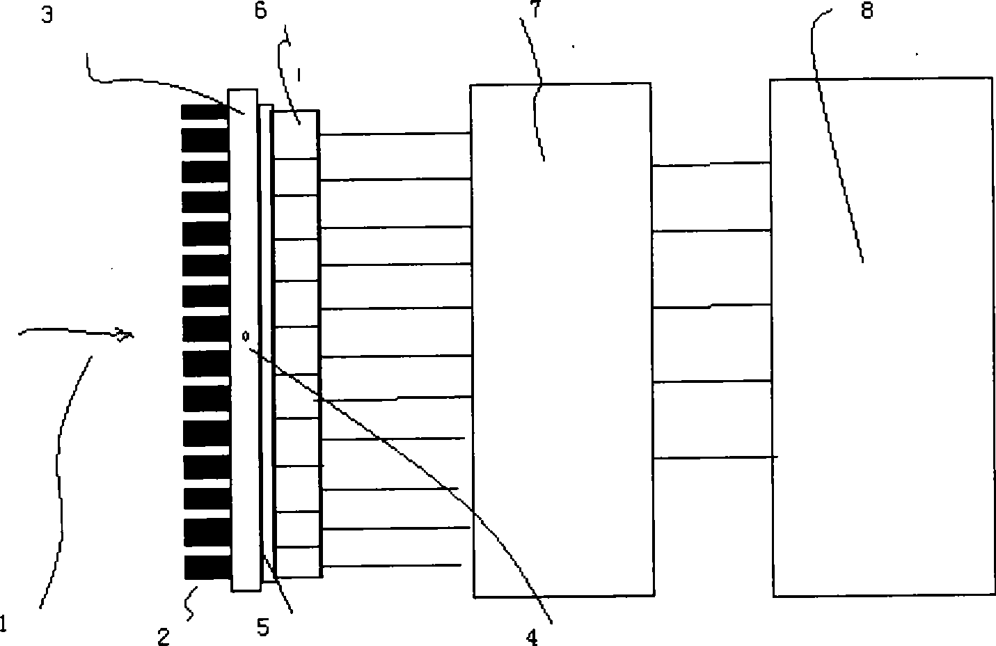
[0031] see Figure 1-Figure 6 , the working process of the present invention is: gamma photons 1 enter the scintillation crystal 3 through the collimator 2, cause the scintillation event 4 on the crystal 3, the fluorescence generated by the scintillation event 4 is collected by the photomultiplier tube array 6 through the light guide 5, and photomultiplied The signal generated by the tube array is collected by the data acquisition module 7 and then sent to the positioning module 8 for positioning calculation, so as to determine the specific coordinates of the scintillation event 4 on the scintillation crystal 3, record the coordinate information, form a data matrix, and then convert it into an image.

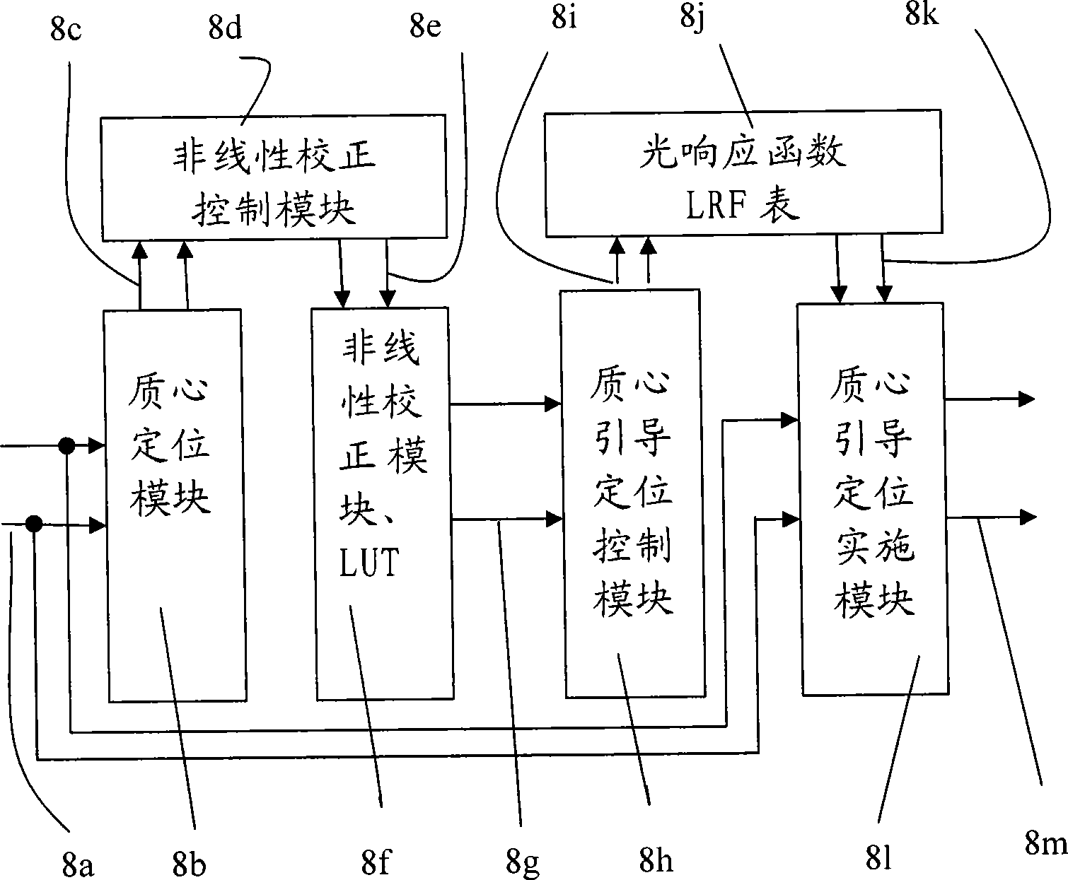
[0032]The working process of the positioning module is: the fluorescent digital signal 8a formed by the data acquisition module is calculated by the centroid positioning method module 8b to obtain a preliminary positioning result 8c, and then 8c enters the nonlinear correction co...


PUM


Abstract

The invention relates to a single photon fault imaging method and system, the method can acquire Gamma photons by a photomultiplier tube array through collision on a scintillation crystal to generate a fluorescent signal, the fluorescent signal is converted into a fluorescent digital signal by a data acquisition module, the fluorescent digital signal is sent into a positioning module to perform positioning calculation, the positioning data can be formed and all effective data can be converted into images, the algorithm adopted in the positioning calculation is maximum likelihood positioning algorithm guided by a mass center, at first the Gamma photon collision position can be calculated with a mass center method, then the Gamma photon collision positioning data can be formed by accurately estimating with local two-dimension maximum likelihood method in a selected scope; the system comprises the scintillation crystal, the photomultiplier tube array, the data acquisition module, the positioning module and an imaging module. The positioning accuracy of the invention is approximate to the maximum likelihood positioning method, thereby shortening the calculating time and reducing the requirements for the computer hardware and the memory space greatly.

Description

technical field [0001] The present invention relates to a single-photon tomographic imaging method, and also relates to a single-photon tomographic imaging system using this method, which can be mainly used for clinical diagnosis of diseases, monitoring of nuclide treatment process and scientific research (including animal imaging system), etc. . Background technique [0002] Single-photon emission computed tomography (SPECT) is an important disease diagnostic equipment and can be used to monitor the nuclide treatment process. It receives gamma rays through scintillation crystals, and produces fluorescent flashes at the collision positions of gamma photons. The photomultiplier tube array behind the scintillation crystal receives the fluorescent flashes, generates corresponding fluorescent signals, and converts the fluorescent signals into fluorescent digital signals through the data acquisition module and sends them to the positioning module for positioning calculation, form...

Claims


Application Information

Patent Timeline
IPC IPC(8): A61B6/03
Inventor 蔡白银曹文田包尚联
Owner 北京海思威科技有限公司
Learn More