Fume exhaust ventilator and range integrated machine

An all-in-one machine and range hood technology, which is applied in the direction of removing lampblack, household stoves, household appliances, etc., can solve the problems of closing the suction port, disturbing the stove, increasing costs, etc., and achieves the solution of outdoor wind backflow, high safety, Effect of preventing water from entering the suction port

Active Publication Date: 2009-06-10
ZHEJIANG MEIDA IND CO LTD
View PDF2 Cites 0 Cited by
  • Summary
  • Abstract
  • Description
  • Claims
  • Application Information

AI Technical Summary

Problems solved by technology

However, the simple lift cannot open or close the suction ring, and this document does not disclose how to open or close the suction ring, so this document still does not solve the problem of closing the suction port when not in use
Secondly, the lifting suction ring wraps around the stove, and the lifting suction ring also forms the wall of the stove hole, and rises and falls together, and the stove placed on the stove is disturbed, which affects safety.
In addition, in the case of multi-hole cookers, each lifting ring needs to be equipped with a motor, which increases the cost

Method used


Image

  • Fume exhaust ventilator and range integrated machine
  • Fume exhaust ventilator and range integrated machine
  • Fume exhaust ventilator and range integrated machine

Examples


Embodiment 1

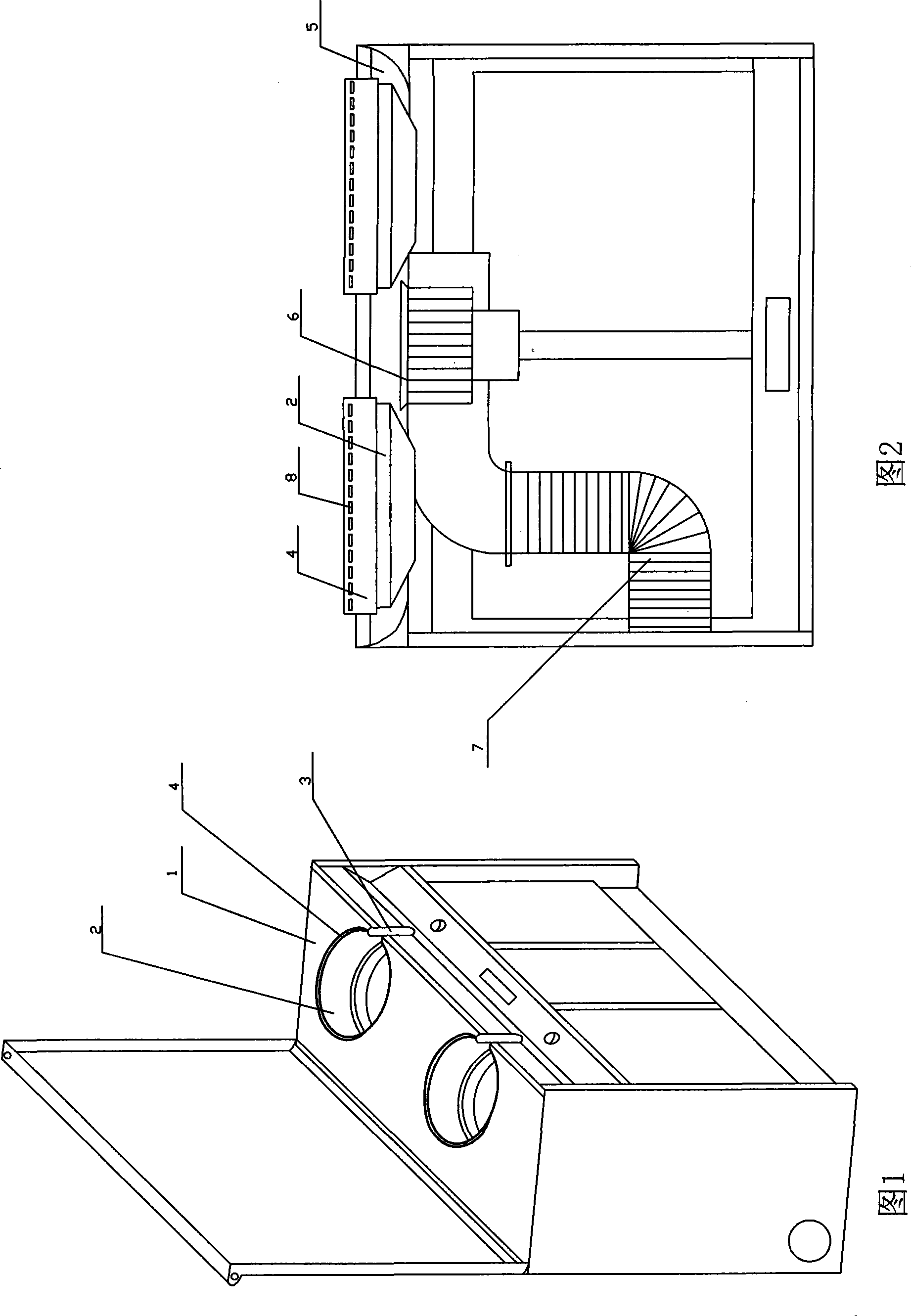
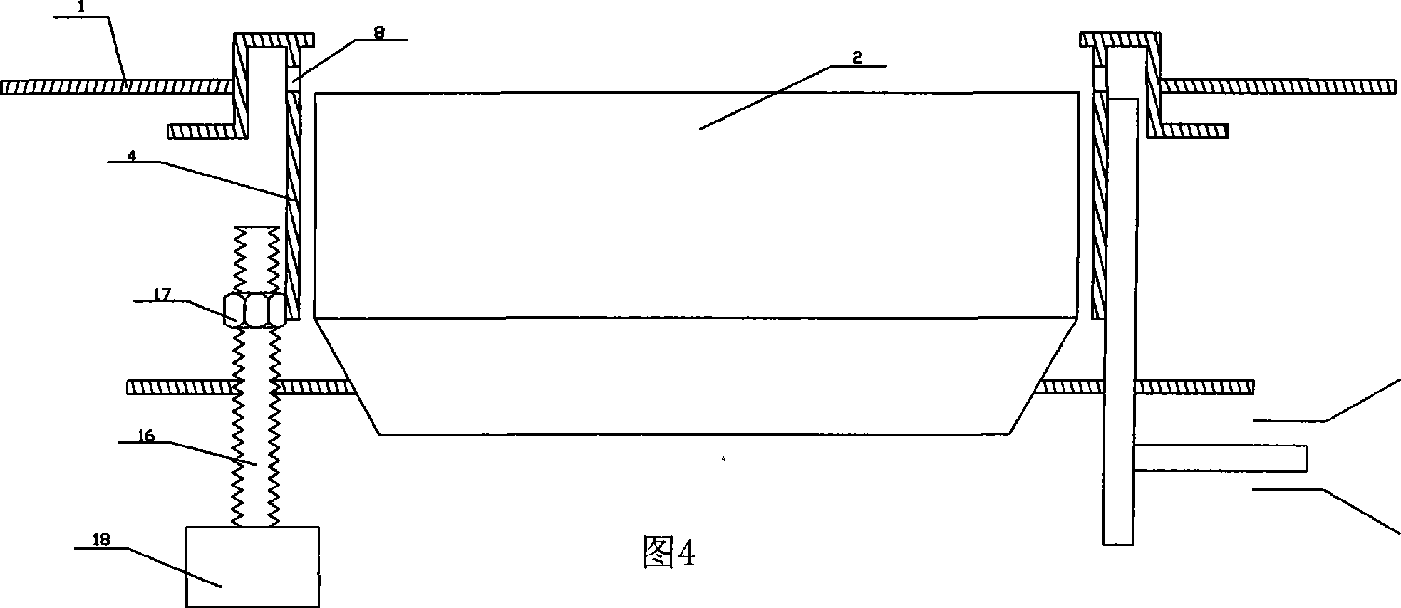
[0028] The range hood integrated machine of the present invention includes a cabinet-type body, the panel 1 of the body is provided with a concave stove hole 2, the bottom plate of the stove hole barrel 2 is provided with a stove, and the stove hole barrel 2 There is a handle hole 3 on the side facing people, the air inlet of the fan 6 is arranged in the gas collecting box 5, and the fan 6 is also connected to the exhaust pipe 7.

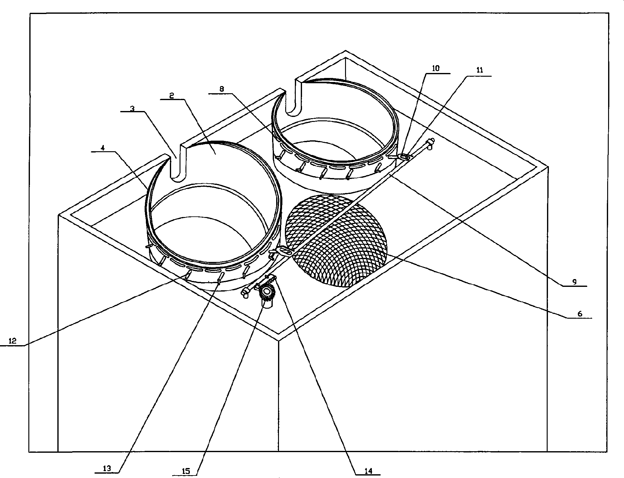
[0029] The lifting ring 4 is slidably connected to the outer surface of the wall of the stove hole, the outer wall of the lifting ring 4 is sealed with the panel 1, and the inner cavity of the lifting ring 4 communicates with the gas collection box 5, and is exposed when the lifting ring 4 is raised. The inner part of the lifting ring 4 of the wall of the stove hole is provided with an air suction port 8, and the lifting ring 4 is connected with a lifting drive mechanism.

[0030] The lifting drive mechanism includes: a horizontally movable pull rod...

Embodiment 2

[0042] The difference between this embodiment and the first embodiment lies in the connection method between the lifting ring and the pull rod. In this embodiment, the lifting ring 4 has a chute 10, and the pin 11 connected to the pull rod 9 is set in the chute 10. Inside. All the other are the same as the first embodiment.

Embodiment 3

[0044] The difference between the present embodiment and the first embodiment lies in the lifting drive mechanism, the drive mechanism of the present embodiment is a rack 19, the rack 19 meshes with a gear, and the gear is driven by a motor.

[0045] All the other are the same as the first embodiment.

[0046] When the suction port is to be closed, the rack 19 pulls the lifting ring 4 to slide down along the wall of the stove hole until the suction port 8 on the lifting ring 4 is covered by the wall of the stove hole.

[0047] When the suction port needs to be opened, the rack 19 pulls the lifting ring 4 to slide upwards along the wall of the stove hole.


PUM


Abstract

The invention relates to an integrative cooking utensils of lampblack absorber and cooker, comprising a cabinet body, a plurality of cylindrical sunken stove holes are formed in the panel of the body, a cooker is provided on the soleplate of the stove holes, a handle hole in one side of the stove holes faces person, the air inlet of a blower is set in the gas collecting tank. The blower is connected with an exhaust pipe; a lifting ring can be connected to the outer face of wall of the cooking stove sleeve in sliding way, and the cavity of the lifting ring is connected with the gas collecting tank; when the lifting ring lifts, inside part exposed from wall of the cylindrical stove holes is opened with an air suction port, and the lifting ring is connected with a driving mechanism so as to avoid the outside air from flowing back.

Description

(1) Technical field [0001] The invention relates to a range hood integrated machine. (2) Technical background [0002] The effect of the range hood is related to the distance from the suction port to the source of the oil fume. Generally, the range hood is an upper exhaust type. The range hood is installed above the stove. The distance from the suction port to the source of the oil fume is usually 50-100 cm. It is easy to cause oil fumes to escape, affecting human health and environmental sanitation. [0003] Chinese patent ZL02234971.5 discloses an integrated range hood and cooker. The integrated range hood and cooker is a combination of a range hood and a cooker. On the wall, the distance for the free diffusion of oil fume is reduced, and the absorption rate of oil fume is improved. However, the suction port of this reference document cannot be closed, which is insufficient. The wall of the stove hole needs to be cleaned frequently. Water, oil and other debris can easil...

Claims


Application Information

Patent Timeline
Patent Type & Authority Applications(China)
IPC IPC(8): F24C15/20
CPCF24C15/2042
Inventor 夏志生
Owner ZHEJIANG MEIDA IND CO LTD
Why Eureka
Try Eureka