Method and device for finish-machining spherical ingot

A technology for spherical blanks and processing steps, which is applied in the field of spherical blank processing, can solve the problems that have not been reported, the accuracy and efficiency are difficult to meet the requirements, etc., and achieve the effects of improving workpiece accuracy and work efficiency, easy automatic control, and ensuring surface smoothness

Inactive Publication Date: 2009-06-17
TSINGHUA UNIV +1
View PDF0 Cites 10 Cited by
  • Summary
  • Abstract
  • Description
  • Claims
  • Application Information

AI Technical Summary

Problems solved by technology

If it is operated with the existing manual lathe, it is difficult to meet the requirements in terms of precision and efficiency
German NUKEM company has the ability to produce spherical fuel elements, but its spherical finishing method and equipment have not been reported yet

Method used


Image

  • Method and device for finish-machining spherical ingot
  • Method and device for finish-machining spherical ingot
  • Method and device for finish-machining spherical ingot

Examples


Embodiment 1

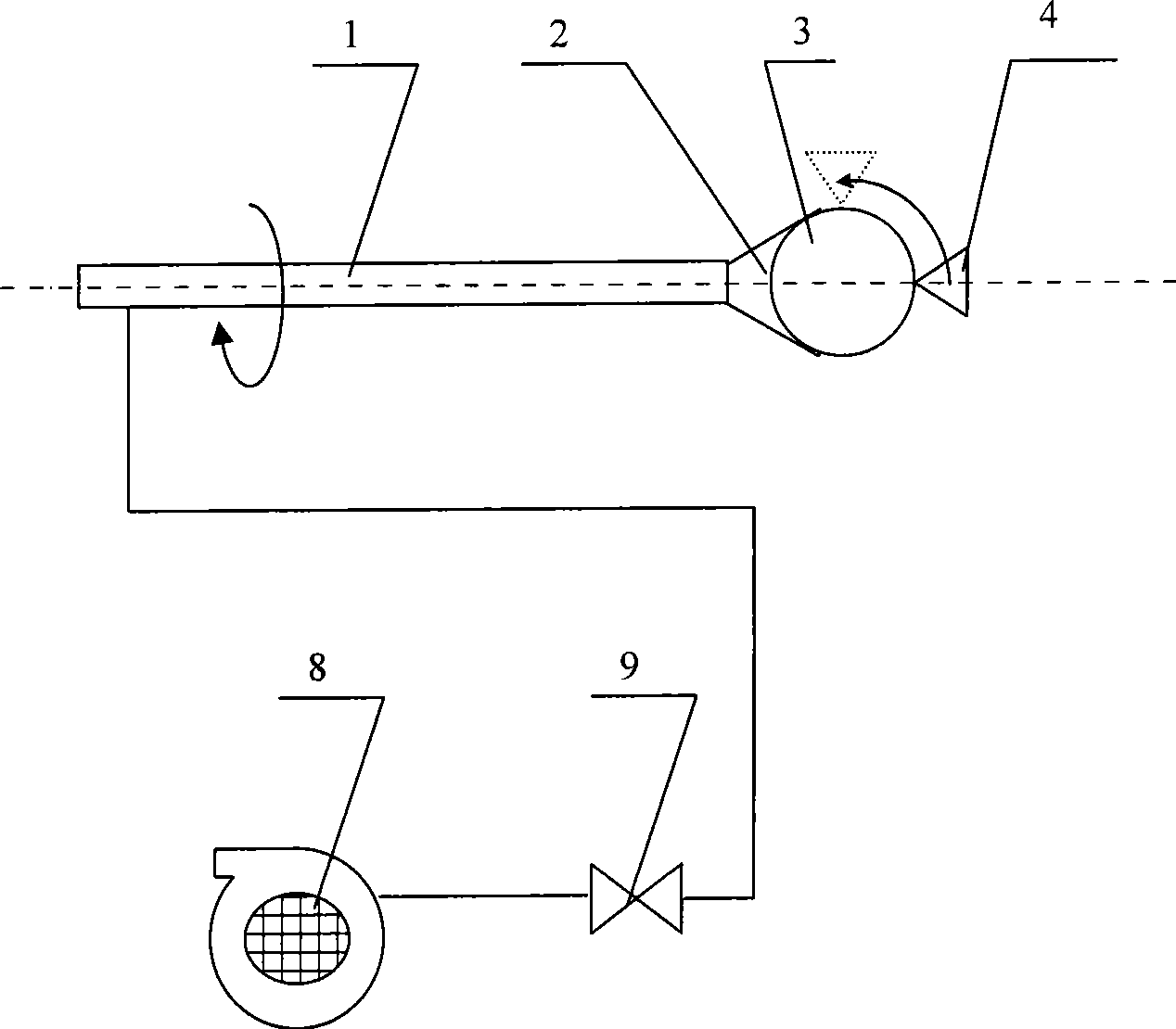
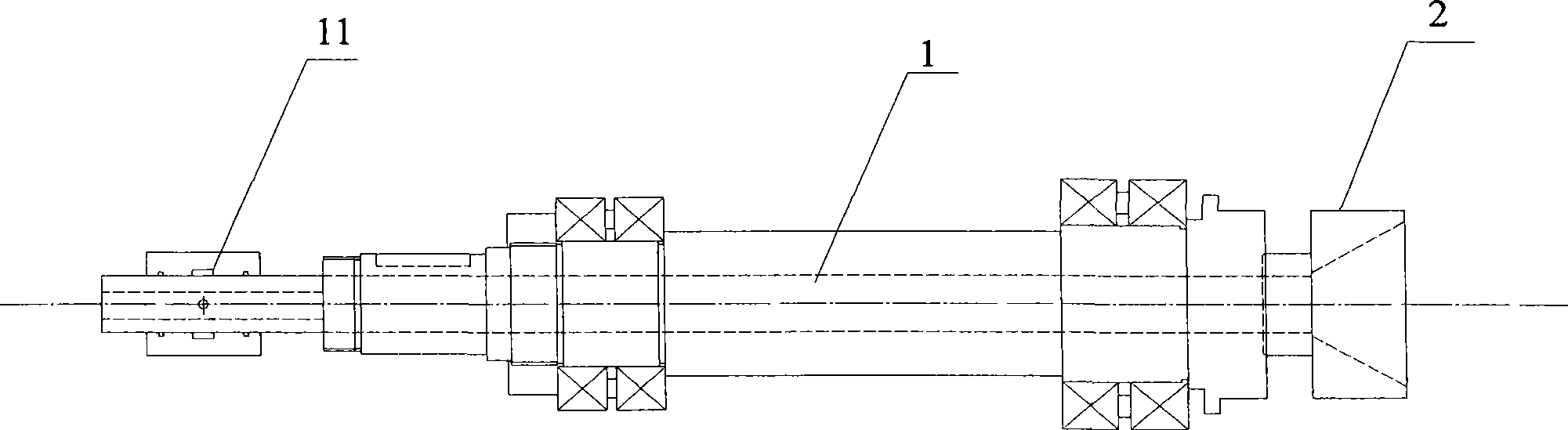
[0025] figure 1 It is a schematic structural view of the device in the form of a single spindle in the present invention. One end of the hollow main shaft 1 is installed with a trumpet-shaped vacuum suction cup clamping tool 2, and the main shaft tool 4 performs a lateral feed movement in the direction of the center line of the main shaft 1 or a 90° arc-shaped movement in the plane of the main shaft 1; the main shaft The other end of the valve is connected with the electromagnetic valve 9 and the vacuum pump 8 in turn through the moving fit joint 11 and the vacuum pipeline.

[0026] When processing the billet, first start the vacuum pump 8, open the solenoid valve 9 to conduct the vacuum pipeline, and then place the billet 3 on the clamping tool 2; after the billet 3 is fixed, the spindle 1 starts to rotate around the axis, and at the same time The tool holder drives the spindle tool 4 to feed the ball blank 3 along the axis; after the feed is in place, the tool 4 takes the c...

Embodiment 2

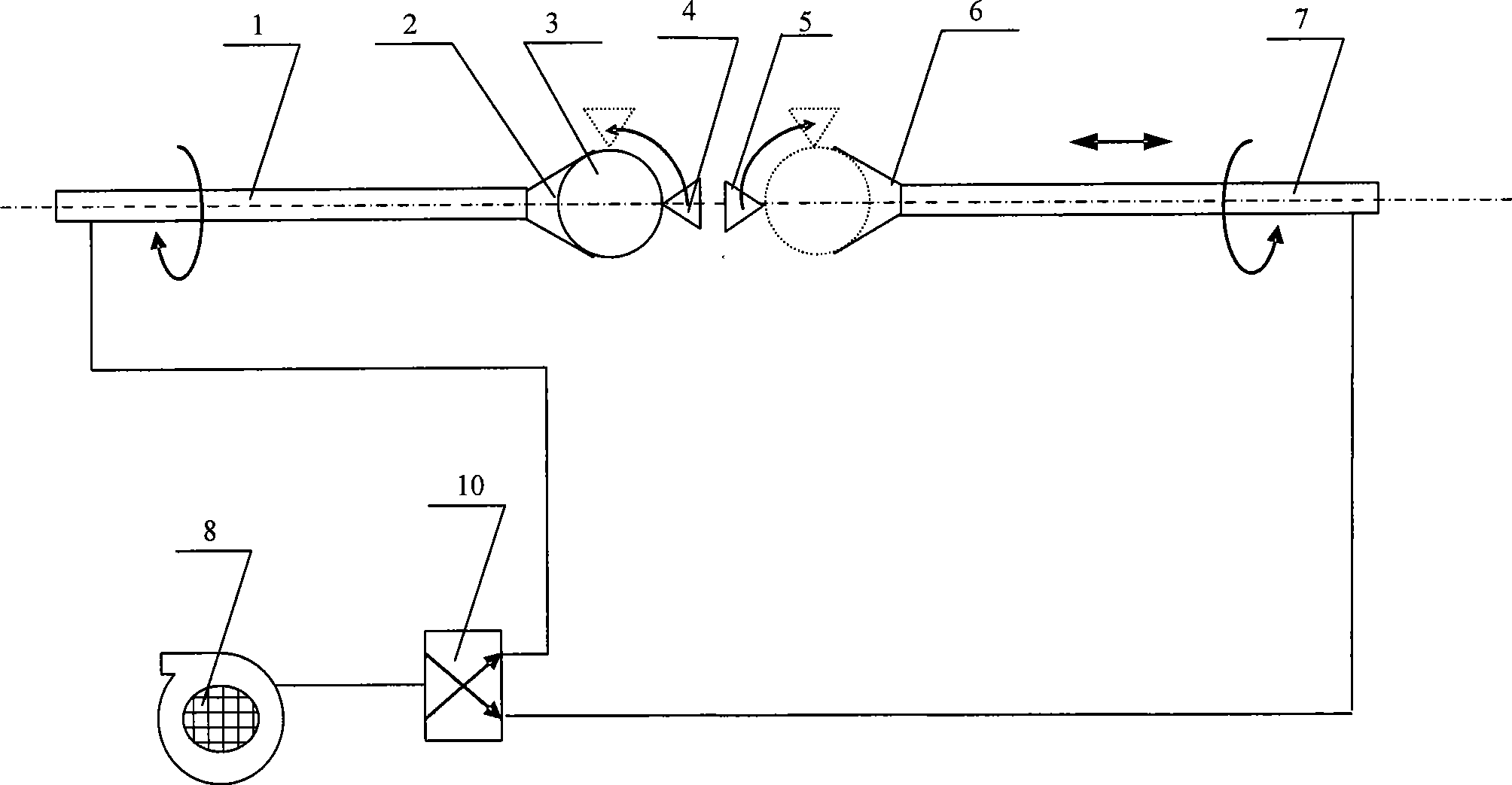
[0028] figure 2 It is a schematic diagram of the structure of the device in the form of dual spindles in the present invention. One end of the hollow main shaft 1 is installed with a trumpet-shaped vacuum suction cup clamping tool 2, and the main shaft tool 4 performs a lateral feed movement in the direction of the center line of the main shaft 1 or a 90° arc-shaped movement in the plane of the main shaft 1; the main shaft 1 is fixed in the direction of its axis and only rotates around its axis.

[0029] The sub-spindle 7 with the same structure as the main shaft 1 is on the same axis as the main shaft 1, and the end of the sub-spindle 7 close to the ball blank 3 is provided with a vacuum suction cup type sub-spindle clamping tool 6, and the sub-spindle tool 5 is formed along the center line of the sub-spindle 7. Lateral feed movement or 90° arc-shaped movement in the plane where the sub-spindle 7 is located; both the main shaft 1 and the sub-spindle 7 are connected to the e...


PUM

PropertyMeasurementUnit
diameteraaaaaaaaaa

Abstract

The invention relates to the technical field of ball blank processing, in particular to a method and a device for mechanically processing a high-temperature gas-cooled reactor fuel element ball blank or graphite ball blank. A main shaft holds the ball blank to rotate along an axial lead, a cutter is fed and reaches in place to move in a plane of the main shaft using a ball center of the ball blank as a circle center in an arc shape of 90 degrees, so as to finish semi-ball processing, and finishing of the whole ball blank can be finished through twice semi-ball processing. The device system can ensure even cutting of the whole ball blank, so as to ensure that a fuel-free area of fuel element produces eccentricity due to machining; in addition, when the method and the device are used for processing, surface finish can be ensured by feeding speed; the whole operating process is easy to realize automatic control, particularly when a double-shaft mechanism with the characteristics is adopted, the processing of two semi-balls can be finished continuously; and compared with the prior machine tool, precision of work pieces and working efficiency are improved greatly.

Description

technical field [0001] The invention relates to the technical field of processing spherical blanks, in particular to a method and a device for machining high-temperature gas-cooled reactor fuel element spherical blanks or graphite spherical blanks. Background technique [0002] To process spheres on existing ordinary lathes, both hands are generally used to control the movement of the horizontal and vertical slides of the tool post, or the longitudinal movement of the slides is motorized, and the lateral movement is controlled by hand with the handwheel so that the turning tool runs according to the expected trajectory. , After the outer sphere of the turning tool is basically formed, the shape to be turned is obtained by leaning on the outer spherical surface of the forming knife. In this way, the turned ball is very irregular, the precision is low, and the processing efficiency is low and the scrap rate is high. [0003] High-temperature gas-cooled reactor spherical fuel e...

Claims


Application Information

Patent Timeline
Patent Type & Authority Applications(China)
IPC IPC(8): B23B5/40B23Q5/22B28D1/16
Inventor 邱学良卢振明张杰贺俊秦建国江涛
Owner TSINGHUA UNIV
Why Eureka
Try Eureka