Micro scroll vane and method for producing micro scroll vane substrates

A manufacturing method and blade technology, applied in the manufacture of microstructure devices, microstructure technology, microstructure devices, etc., can solve the problems that cannot be related to scroll micro compressors, etc.

Inactive Publication Date: 2009-06-17
俞度立
View PDF0 Cites 5 Cited by
  • Summary
  • Abstract
  • Description
  • Claims
  • Application Information

AI Technical Summary

Problems solved by technology

Various MEMS pump and compressor ideas have been propo

Method used


Image

  • Micro scroll vane and method for producing micro scroll vane substrates
  • Micro scroll vane and method for producing micro scroll vane substrates
  • Micro scroll vane and method for producing micro scroll vane substrates

Examples


Embodiment Construction

[0035] Below in conjunction with accompanying drawing, the present invention is described in further detail:

[0036] In conventional large-scale compressor applications, the scroll and motor are two separate components, and the delivery of driving torque is achieved through a crankshaft or other connecting mechanism. In order to prevent the rotation of the movable scroll, an Oldham ring is added. General formulas for calculating force, torque, power, etc., have been listed in Reference 1. A more detailed calculation method such as using the finite element method has been introduced in Document 2. These formulas and methods can provide optimized design parameters. Due to the unique driving method of the present invention, there is no need to add Oldham rings (if necessary, Oldham rings can be added very easily). Eliminating Oldham rings reduces friction.

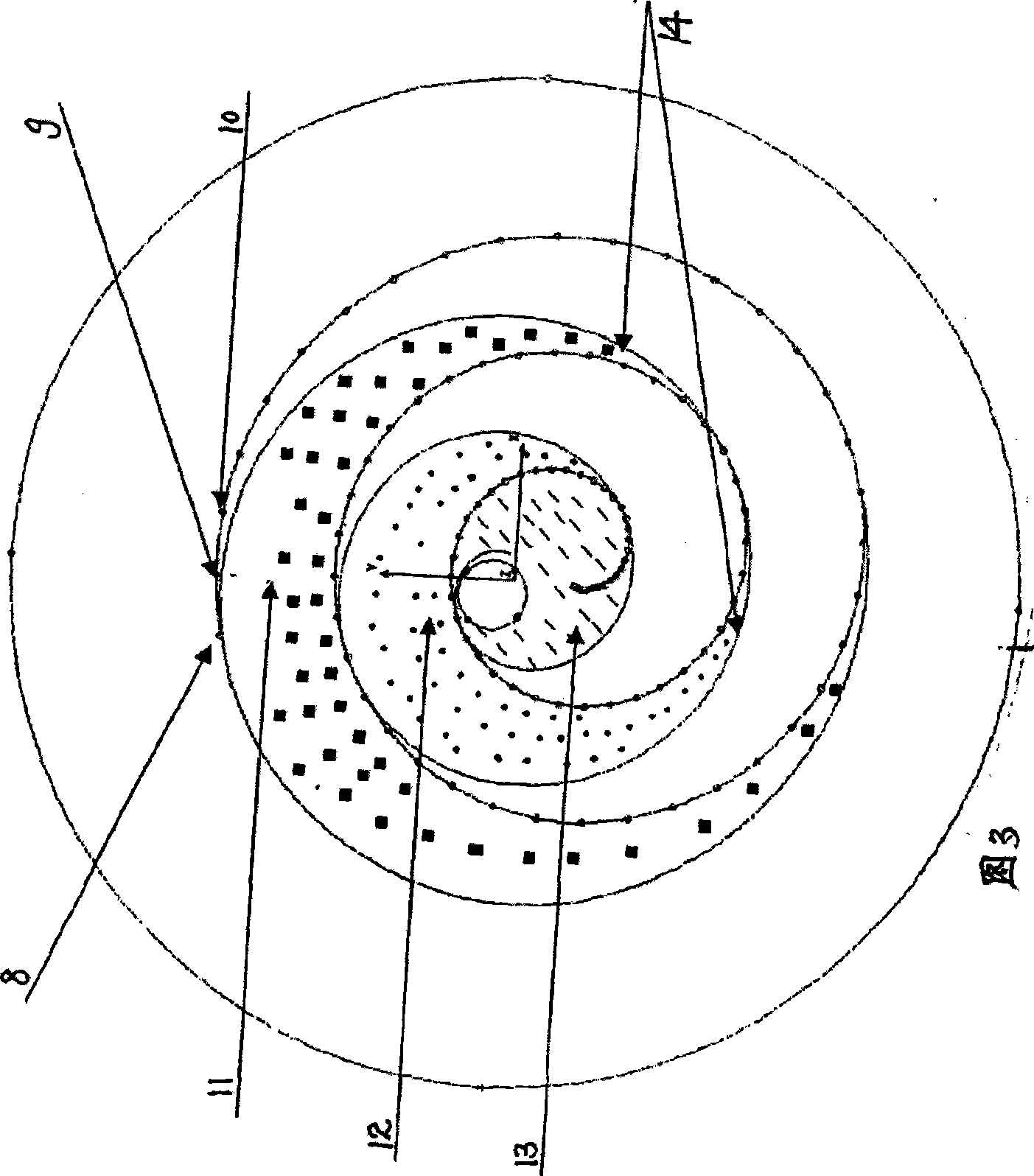
[0037] In Figure 3, the electrostatic force attracts the movable scroll to the fixed scroll, forming an initial contac...


PUM


Abstract

The invention relates to a method for manufacturing a micro scroll blade and a micro scroll substrate. The method for manufacturing the micro scroll blade comprises the following steps: a, using an SOI silicon chip as an initial material; b, nonisotropically etching the silicon chip to form a curve and a scroll blade; and c, stopping etching on a silicon dioxide layer on the silicon chip. The method for manufacturing the micro scroll substrate comprises the following steps: a, using the SOI silicon chip as the initial material; b, deeply etching the silicon chip on the front to form a blade; c, stopping unidirectional etching on a silicon dioxide film layer; and d, etching the silicon chip from the back by deep reaction plasma, and stopping etching on the silicon dioxide layer. The micro scroll blade is a micro scroll wall.

Description

[0001] The invention application is a divisional application of the original application; [0002] The name of the original application is: "Micro-machined scroll compressor and related technologies"; the application number is: 200510080192.2; the application date is: July 4, 2005 technical field [0003] The invention relates to the micro-machining technology of a micro-electromechanical system, in particular to a manufacturing method of a micro-scroll blade and a micro-scroll substrate in a micro-scroll device. Background technique [0004] The concept of the scroll compressor was proposed by Creux in 1905. Due to the need for nearly perfect conjugated helix design and processing, the error must be controlled within a few microns. Therefore, until the application of computer-controlled precision machining in the 1970s, it could not be put into practice for a long time. In addition to the aforementioned manufacturing difficulties, design issues such as wear and leakage pre...

Claims


Application Information

Patent Timeline
IPC IPC(8): B81C1/00F04C18/02F04C27/00
Inventor 俞度立
Owner 俞度立
Why Eureka
Try Eureka