Hydrophile guard rail at bank edge

A guardrail and hydrophilic technology, applied in the direction of fences, water aeration, water/sludge/sewage treatment, etc., can solve the problem of no effect on improving water bodies

Inactive Publication Date: 2009-06-17
杨照军
View PDF0 Cites 1 Cited by
  • Summary
  • Abstract
  • Description
  • Claims
  • Application Information

AI Technical Summary

Problems solved by technology

[0002] The traditional hydrophilic guardrail on the shore only plays the role of protection and viewing, and has no effect on improving the water body

Method used


Image

  • Hydrophile guard rail at bank edge

Examples


Embodiment Construction

[0010] The present invention is illustrated below in conjunction with accompanying drawing.

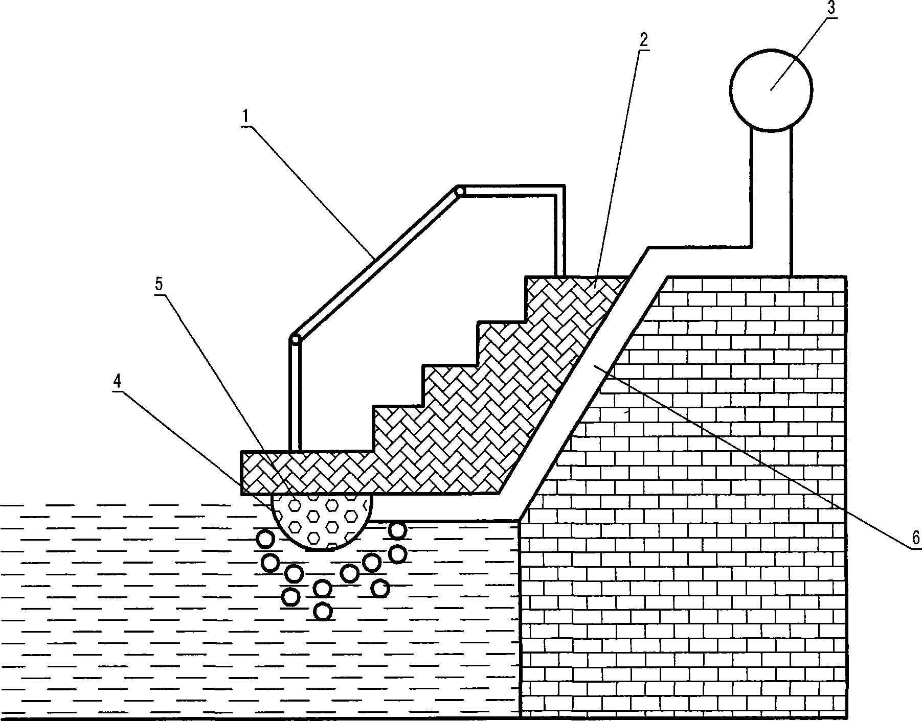
[0011] The present invention comprises step 2 and guardrail 1, is provided with air storage tank 3 on the shore, wherein is filled with compressed air. An aeration ball 4 is arranged at the underwater bottom of the step, and an air storage tank provided on the bank is connected to the aeration ball through a pipeline 6 . The aeration ball is provided with at least one vent hole 5 that makes the inside and outside the same.

[0012] After the air in the air storage tank enters the aeration ball through the trachea, it enters the water through the vent holes on the aeration ball, forming many bubbles, and oxygenating the water body. After the dissolved oxygen in the water increases, aerobic microorganisms can survive and reproduce, and decompose the pollutants in the water. The increase of dissolved oxygen in water will promote the growth of algae and plankton. At the same time, a lar...


PUM


Abstract

The invention relates to a shore-side hydrophilic guard rail, which comprises steps and a guard rail. An air tank is arranged on the shore and an aeration balloon is arranged at the bottom of the steps underwater. The air tank and the aeration ball are connected through a pipeline. The aeration ball is at least provided with a through hole communicating the inside with the outside. The aeration ball supplies oxygen to a water body to increase oxygen dissolved in water to promote the reproduction of aerobic microorganisms that decompose pollutant in the water body, thereby improving water quality and purifying the water body.

Description

technical field [0001] The invention relates to a guardrail, in particular to a hydrophilic guardrail on a bank which can purify water bodies. Background technique [0002] The traditional hydrophilic guardrail on the shore only plays the role of protection and viewing, and has no effect on improving the water body. Contents of the invention [0003] The object of the present invention is to provide a hydrophilic guardrail on the shore which can purify the water body. [0004] Technical scheme of the present invention is: [0005] The invention includes steps and guardrails, an organ air storage tank is arranged on the shore, and an aeration ball is arranged at the bottom of the underwater steps, and the air storage tank and the aeration ball are connected through pipelines. [0006] At least one air hole is provided on the aeration ball to make the inside and outside the same. [0007] Advantage and positive effect of the present invention are: [0008] Oxygenate the ...

Claims


Application Information

Patent Timeline
Patent Type & Authority Applications(China)
IPC IPC(8): C02F3/02C02F7/00E04H17/14
CPCY02W10/10
Inventor 杨照军粟海任宽宋大伟贾彤张宁
Owner 杨照军
Why Eureka
Try Eureka