Band-gap reference voltage circuit

A reference voltage and circuit technology, which is applied in the field of bandgap reference voltage circuits, can solve problems such as difficulty in integration, high cost, and difficulty in ensuring circuit integration, and achieve the effect of overcoming difficulty in integration and simple structure

Inactive Publication Date: 2009-06-17
SUNPLUS TECH CO LTD +1
View PDF2 Cites 9 Cited by
  • Summary
  • Abstract
  • Description
  • Claims
  • Application Information

AI Technical Summary

Problems solved by technology

But it is more difficult to integrate larger R or C into the chip
[0007] Although in the prior art, the accuracy of the voltage signal output by the chopper circuit 12 is improved by various means, such as eliminating the offset voltage and 1/f noise in the operational amplifier of the chopper circuit 12, it still needs to be filtered by RC The circuit 14 filters the voltage signal output by the output chopper circuit 12, so there is still a problem that it is difficult to achieve integration due to the large R or C
[0008] For example, U.S. Patent US20070152740 discloses a low-power bandgap reference voltage circuit for improving accuracy and reducing area overhead. Although this patent application can improve the accuracy of the voltage signal after chopping processing at low-vol

Method used


Image

  • Band-gap reference voltage circuit
  • Band-gap reference voltage circuit
  • Band-gap reference voltage circuit

Examples


Embodiment Construction

[0048] In order to make the object, technical solution and advantages of the present invention clearer, the present invention will be further described in detail below with reference to the accompanying drawings and examples.

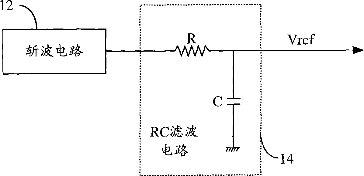
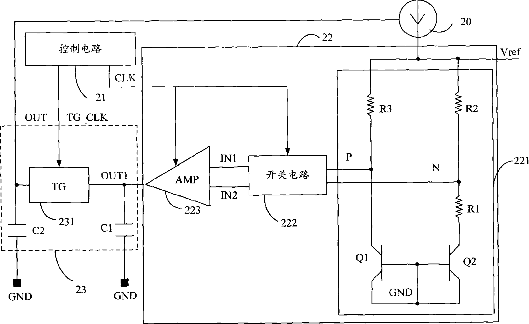
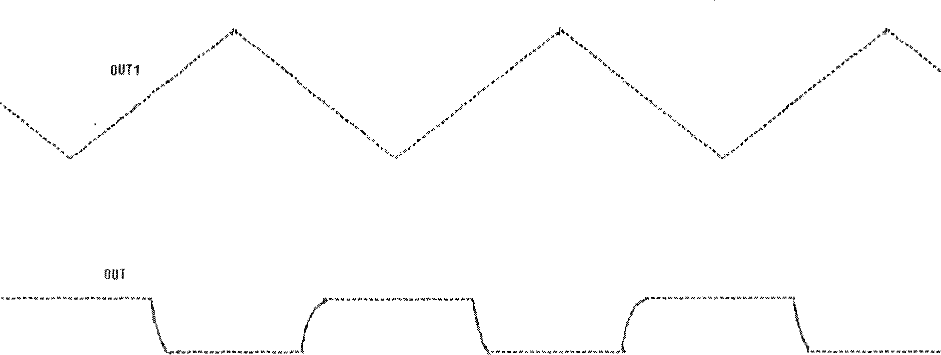
[0049] The invention adopts a combination circuit of a TG switch and a capacitor to replace the RC filter circuit in the existing bandgap reference voltage circuit, and filters the voltage signal output by the chopper circuit to eliminate the ripple of the voltage signal. At the same time, the present invention further reduces the ripple of the output voltage signal of the chopper circuit by increasing the switching frequency in the chopper circuit.

[0050] Among them, the combination circuit of TG switch and capacitor is used to filter the voltage signal, and the charging and discharging time of the filter capacitor after the switch can be controlled by controlling the frequency of the TG switch, so that there is no need to set a large R or C, which ov...


PUM


Abstract

The invention discloses a band gap basic voltage circuit that uses a combined circuit of TG switch and capacitance for displacing RC filter circuit in existing band gap basic voltage circuit, and controls output voltage ripples by controlling turn-on time of TG switch for realizing filtering of voltage signal, accordingly, larger R or C is not needed and can overcome problem that RC filter circuit is difficult to integration, and the combined circuit of TG switch and capacitance has simple structure. A chopper circuit has higher switch frequency, and can act on filtering, increase stability of basic voltage further.

Description

technical field [0001] The invention relates to integrated circuit technology, in particular to a bandgap reference voltage circuit based on a chopper circuit and a switch filter circuit. Background technique [0002] The existing bandgap reference voltage circuit is usually composed of a chopper circuit, a control circuit and an RC filter circuit. Such as figure 1 As shown, the chopper circuit 12 receives the voltage signal provided by the constant current source, performs chopping processing on the voltage signal, and then outputs it to the resistor-capacitor (RC) filter circuit 14 through its input terminal. [0003] In practical applications, the chopper circuit 12 usually includes a proportional to absolute temperature (PTAT) circuit, a switch circuit, and an operational amplifier (not shown in the figure). Wherein, the switch circuit receives the voltage signal output by the PTAT circuit, and the switch circuit and the operational amplifier circuit cooperate to chop ...

Claims


Application Information

Patent Timeline
IPC IPC(8): G05F3/16
Inventor 李欣陈正原
Owner SUNPLUS TECH CO LTD
Why Eureka
Try Eureka