Flat oscillating motor

A vibration motor, flat type technology, used in electric components, magnetic circuit rotating parts, electromechanical devices, etc., can solve problems such as increased vibration, poor wire breakage, shortened motor life, etc., to prevent deformation of the coil and prevent breakage. The effect of poor line and not easy to deform

Inactive Publication Date: 2009-06-17
WENDENG YONGBAI MICRO MOTOR CO LTD +1
View PDF0 Cites 8 Cited by
  • Summary
  • Abstract
  • Description
  • Claims
  • Application Information

AI Technical Summary

Problems solved by technology

[0008] Because the vibrator (26) imparts eccentricity to the rotor (20), it should be made of high specific gravity metal. Therefore, the center of the weight of the rotor (20) and the vibrator (26) is concentrated on a specific position. Due to this structural characteristic, If the vibrator (26) is strengthened, the vibrator (26) will be detached from the rotor (20) and the center bearing (28) will also be detached from the body (24) formed by resin injection molding. Limit the volume of the vibrator within the

Method used


Image

  • Flat oscillating motor
  • Flat oscillating motor
  • Flat oscillating motor

Examples


Embodiment Construction

[0032] As shown in the accompanying drawings, with reference to the following accompanying drawings, the present invention will be described in detail

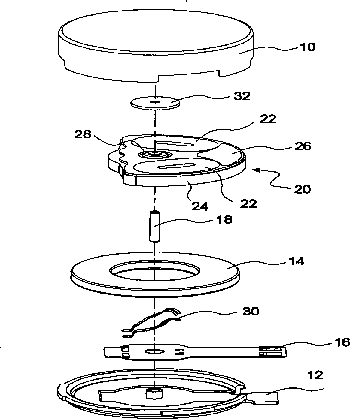
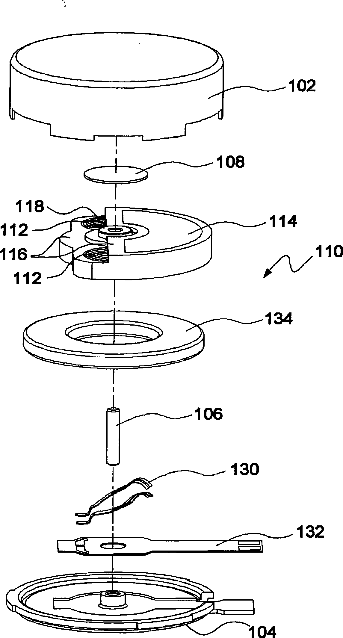
[0033] image 3 It is an exploded perspective view of a flat vibrating motor (100) of the present invention, Figure 4 It is the internal perspective sectional view of the vibrating motor (100), Figure 5 is a plan view of a rotor (110) suitable for a vibration motor (100), Image 6 to press Figure 5 The cross-sectional view viewed by the A-A line, Figure 7 for Figure 5 The bottom view of the rotor (110).

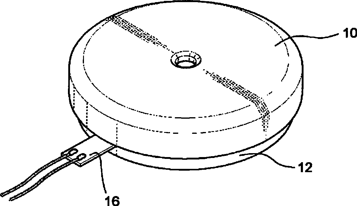
[0034] image 3 and Figure 4 As shown in the figure, the flat vibrating motor (100) comprises a cup-shaped upper casing (102) and a plate-shaped lower casing (104) that seals the inlet of the casing (102), and the casing is made of a metal material to be suitable for pressing In combination, there are grooves and holes in the center of the upper casing (102) and the lower casing (104), and the fixed rotating sha...


PUM


Abstract

The invention discloses a flat type vibrating motor for electronic products which are mobile phones and pagers and the like, wherein the center portion of an upper shell and a lower shell which provide round space in the mutually butted inner portions is perpendicularly fixed with a rotating shaft, the rotating shaft supports a rotor to rotate, the rotor is a flat structure which is integrally formed by two coils and a vibrator with high specific gravity, the two coils are fixed with generation magnetic fields on a printed circuit board which is matched with commutators, the vibrator with high specific gravity is fixed on the upper portion of the coil, the vibrator is tungsten alloy powder with high specific gravity and less quantitative nickel, a circular arc body of the vibrator is subject to a rotating center, more than half of the upper surface of the coil is covered not exceeding the range of 180 degrees, and the lower portion of the rotor is orderly equipped with a permanent magnet and a soft printed winding board, a circular circle of the permanent magnet is equipped with an N pole and an S pole crossways, and the soft printed winding board is connected with an external power supply. One side of an electric brush is fixed on the soft printed circuit board, the other surface contacts with the commutators, the rotor is an integrated structure of resin and metal vibrator with high specific gravity, the resin is used for the upper portion of the coil, a wire casing is formed on the periphery of a bearing, the outer edge of the vibrator is formed into a step shape, the structure of firmly binding with resin injection objects is increased, a hollow core of the coil is also injected by the resin, thereby reducing the coil to deform because of plastic pressure in maximal degree.

Description

Technical field: [0001] The invention relates to electronic devices, in particular to a flat vibrating motor used in electronic products such as mobile phones and pagers. Background technique: [0002] As we all know, mobile communication terminals such as cell phones and pagers use vibrating motors to notify users of incoming calls. At first, the vibrating motors were mainly bar-type motors, but now flat types are widely used. (coin type). [0003] figure 1 with figure 2 Shown is the basic structure of a conventional flat type vibration motor. [0004] figure 1 It is a perspective view illustrating an assembled state of a conventional flat vibration motor, figure 2 It is an exploded oblique view of the vibration motor. [0005] Such as figure 1 , figure 2 As shown, the vibration motor provides an internal space for the press-fit joint of the upper casing (10) and the lower casing (12), and a part of the flexible printed circuit board (16) extends outside the casi...

Claims


Application Information

Patent Timeline
IPC IPC(8): H02K23/68H02K23/66H02K23/04H02K7/065H02K1/27H02K11/00C22C27/04C22C1/04
Inventor 李相宜
Owner WENDENG YONGBAI MICRO MOTOR CO LTD
Why Eureka
Try Eureka