Horizontal rotary compressor

A rotary compressor, horizontal technology, used in rotary piston machinery, rotary piston pumps, rotary piston/oscillating piston pump components, etc. Easy to burn and other problems, to achieve the effect of reducing oil output and uniform cooling

Inactive Publication Date: 2009-06-24
GUANGDONG MEIZHI COMPRESSOR
View PDF0 Cites 11 Cited by
  • Summary
  • Abstract
  • Description
  • Claims
  • Application Information

AI Technical Summary

Problems solved by technology

Under different working conditions of traditional horizontal rotary compressors, the oil level inside the casing fluctuates greatly. As a result, there is insufficient oil supplied to the compression components, which leads to a decrease in the reliability of the compressor and discharge to the system. The increase of oil discharge will reduce the performance of the compressor, and there is also the problem of sacrificing the cooling of the motor winding by the discharge gas in order to control the oil level, resulting in the problem that the motor is easy to burn

Method used


Image

  • Horizontal rotary compressor
  • Horizontal rotary compressor
  • Horizontal rotary compressor

Examples


no. 1 example

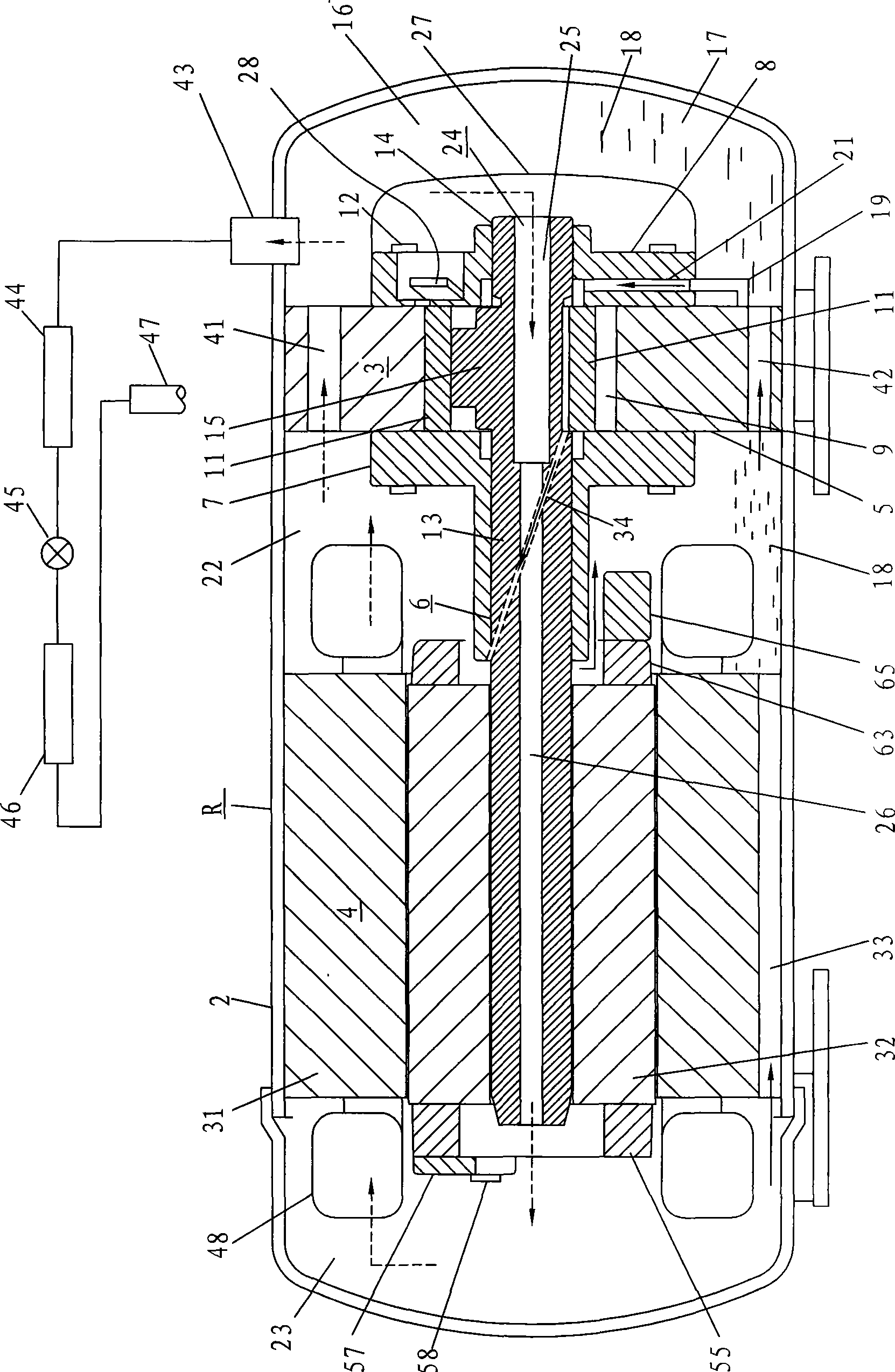
[0021] see figure 1 , the inner diameter of the sealed casing 2 of the horizontal rotary compressor R is fixed and accommodates the compression assembly 3 and the motor 4 . The compression assembly 3 consists of a cylinder 5, a main bearing 7 and an auxiliary bearing 8 that support the crankshaft 6 and are installed on the side of the cylinder 5, a circular piston 11 located at the center of the cylinder 5 and accommodated in the cylinder compression chamber 9, and the outer circumference of the piston. Contact slides (not shown in the figure) form. These components are connected by cylinder screws 12 to form a compression assembly 3 . In addition, the crankshaft 6 is composed of a main shaft 13 , a counter shaft 14 and an eccentric shaft 15 . The piston 11 is installed on the eccentric shaft 15 and revolves in the compression chamber of the cylinder.

[0022] The cylinder outer periphery of the cylinder 5 is in close contact with the inner diameter of the sealed casing 2 w...

no. 2 example

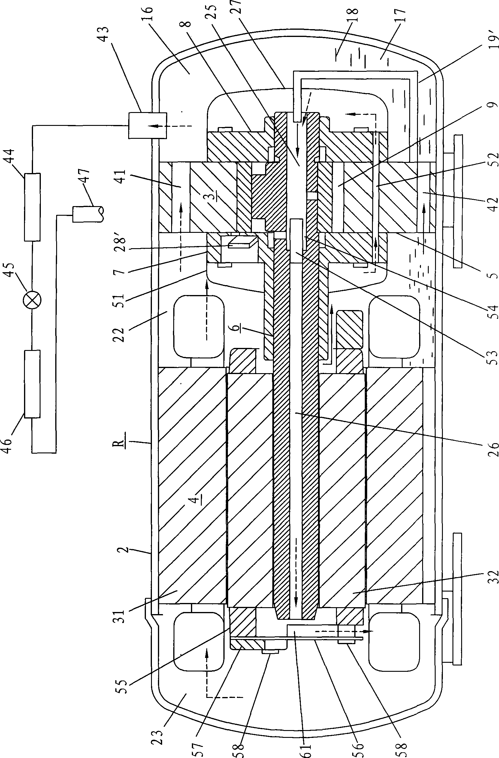
[0036] see figure 2 , the difference between it and the first embodiment will be mainly explained below.

[0037] The main bearing 7 is provided with a second exhaust device 28 ′, which is mounted on the main bearing 7 and covered by a second exhaust muffler 51 . A communication hole 52 is arranged in the cylinder 5, and one end of the communication hole communicates with the second exhaust muffler 51, and the other end communicates with the first exhaust muffler 27, so the high-pressure gas discharged from the cylinder cavity 9 can be exhausted from the second exhaust muffler. The muffler 51 moves into the first exhaust muffler 27 . The other end of the second oil supply pipe 19 ′ connected with the vane pump of the cylinder 5 is installed on the central portion of the first exhaust muffler 27 , and its opening end faces the opening of the first central hole 25 of the crankshaft 6 . Therefore, the oil 18 of the oil sump 17 is supplied into the first center hole 25 of the c...

no. 3 example

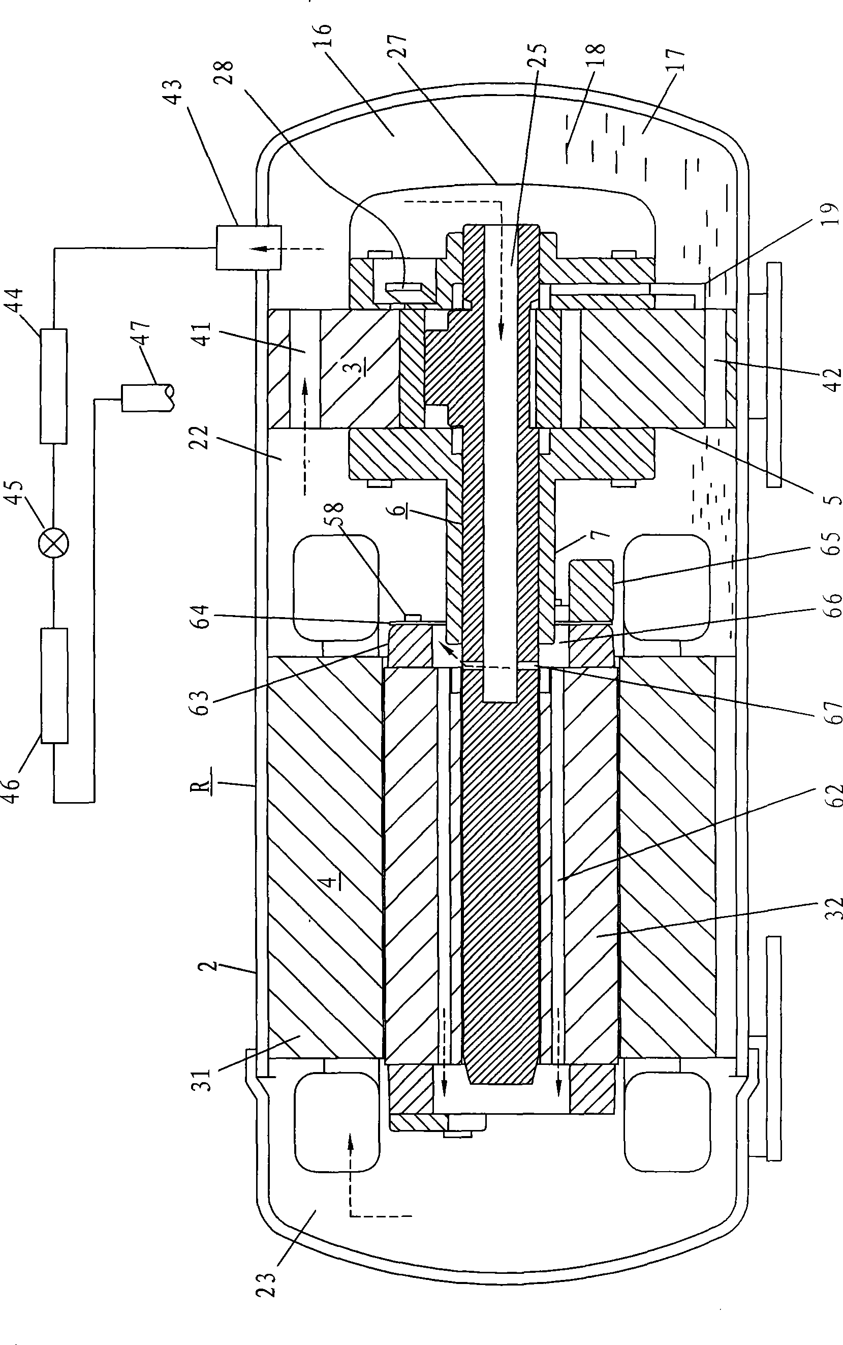
[0045] see image 3 Compared with the first embodiment, the feature of this embodiment is: the high-pressure gas flowing into the first center hole 25 of the crankshaft 6 from the first exhaust muffler 27 flows out to the second through the rotor vent hole 62 penetrating the inside of the rotor 32. Motor chamber 23.

[0046] Like the second embodiment, the first rotor end plate 64 located at the right end of the rotor 32 in the first motor cavity 22 is fixed on the first end ring 63 together with the first balance weight 65 . In order to prevent gas leakage from the gap between the central hole of the first rotor end plate 64 and the outer diameter of the main bearing 7, the gap should be reduced as much as possible. The rotor 32 is located in the inner diameter of the first end ring 63 , and is provided with a plurality of rotor ventilation holes 62 axially penetrating through the rotor 32 . One end of the rotor ventilation hole 62 is opened in the interior of the rotor cha...


PUM


Abstract

The invention relates to a horizontal rotary compressor, comprising a housing, wherein, the inner pressure of the housing is high, and a compression component and an electric motor are arranged in the housing; the compression component and the periphery of the electric motor are respectively fixed on the inner diameter of the housing and divide the interior of the housing into three cavity chambers, i.e. a crank shaft penetration oil cavity, a first electric motor cavity and a second electric motor cavity; more than one incision gaps are arranged between the bottom of a rotor and the inner diameter of the housing, both ends of each incision gap are respectively provided with holes on the first electric motor cavity and the second electric motor cavity, the upper part of an air cylinder is provided with an air passage, the lower part is provided with an oil passage, and the air passage and the oil passage are respectively provided with holes on first electric motor cavity and the oil cavity; and an exhaust muffler is arranged on a main bearing or a supplementary bearing, one end of a communication channel is provided with a hole on the exhaust muffler, the other end is provided with a hole on the second electric motor cavity, and high pressure air and oil exhausted from the compression component are led into the second electric motor cavity by the communication channel. The horizontal rotary compressor can reduce the oil discharge volume, uniformly cool the machine winding and greatly improve the reliability of the compressor.

Description

technical field [0001] The invention relates to a horizontal rotary compressor, in particular to a horizontal rotary compressor whose inner pressure of the shell is high pressure. Background technique [0002] In recent years, with the popularization of rotary compressors in the world, in order to reduce the system volume of air conditioners and refrigeration machines and expand the effective volume of the system, the application of horizontal rotary compressors is increasing. In the traditional horizontal rotary compressor, under different working conditions, the oil level inside the casing fluctuates greatly. As a result, there is insufficient oil supplied to the compression components, which leads to a decrease in the reliability of the compressor and discharge to the system. The increase in the amount of oil discharged leads to a decrease in the performance of the compressor, and there is also a problem that the cooling of the motor winding by the exhaust gas is sacrific...

Claims


Application Information

Patent Timeline
Patent Type & Authority Applications(China)
IPC IPC(8): F04C29/06F04C29/04F04C18/00
Inventor 小津政雄姜晋成梁自强
Owner GUANGDONG MEIZHI COMPRESSOR
Why Eureka
Try Eureka