
Fan yawing test mechanism and fan set testing bench

A test bench, fan technology, used in wind turbines, engine testing, machines/engines, etc.

Inactive Publication Date: 2010-09-15
SANY ELECTRIC CO LTD
View PDF1 Cites 2 Cited by
  • Summary
  • Abstract
  • Description
  • Claims
  • Application Information

AI Technical Summary

Problems solved by technology

The test bench can carry out multiple wind turbine tests at the same time, but there are still major defects: one is that there is no yaw test mechanism, and the yaw performance of the wind turbine cannot be tested; axial force
[0005] However, there are obvious defects in this experimental method: on the one hand, the size of the engine room is large, and it needs to occupy a large space when deflecting, which is not conducive to installation; On the one hand, the wind turbine drag test and the yaw test cannot be carried out at the same time, which increases the test time, reduces the test efficiency, and makes the test operation more complicated
[0006]In addition, in order to improve the fidelity of the test results, it is necessary to simulate the force and moment of the real wind on the fan, the force and moment of the blade on the fan drive shaft, etc. factors, but the existing test bench does not fully meet the requirements

Method used


Image

  • Fan yawing test mechanism and fan set testing bench
  • Fan yawing test mechanism and fan set testing bench
  • Fan yawing test mechanism and fan set testing bench

Examples


Embodiment Construction

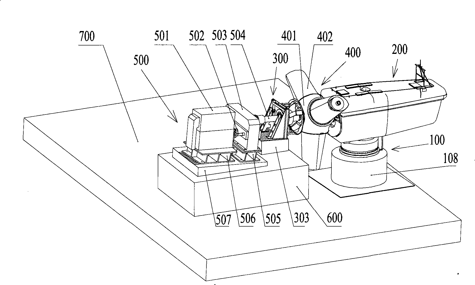
[0063] The basic idea of ​​the present invention is to set up a wind turbine yaw test mechanism; during the wind turbine yaw test, the tower tooling rotates while the engine room is fixed; thus, the wind turbine yaw test can be performed while the prime mover drives the wind turbine to rotate.

[0064] Embodiments of the present invention will be described below in conjunction with the accompanying drawings.

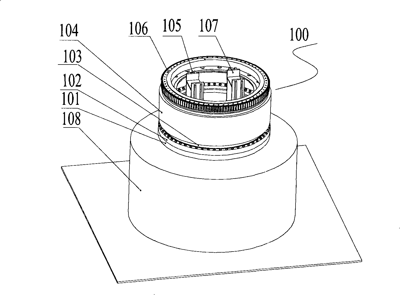
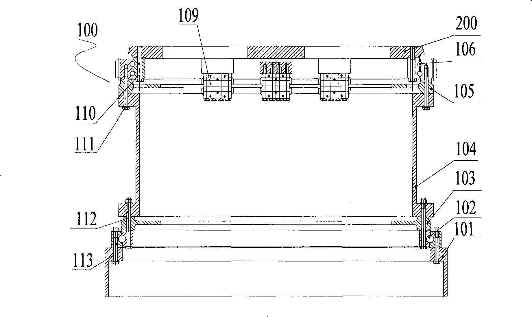
[0065] Please also see figure 1 , figure 2 ,in, figure 1 It is an axonometric view of a preferred embodiment of the fan yaw test mechanism of the present invention; figure 2 yes figure 1 Sectional view along the plane of symmetry of the wind turbine yaw test mechanism. The wind turbine yaw test mechanism 100 includes:

[0066] The nacelle support 107, the lower end is fixed on the yaw foundation 108, and the upper end is fixed to the nacelle of the fan 200;

[0067] The tower tooling 104 is connected with the tower tooling driving device (not shown) through a ...


PUM


Abstract

The invention discloses a yawing testing mechanism for a blower, which comprises a cabin bracket, a tower drum tool, an upper pivoting support, and a lower pivoting support; the lower end part of the cabin bracket is fixed on a yawing base, and the cabin of the blower is fixed at the upper end part; the tower drum tool is connected with a tower drum tool driving device through a transmission mechanism, and rotates around the axis of the tower drum tool under the action of the tower drum tool driving device; the upper pivoting support is mounted at the lower part of an underframe of the cabin,and is used for leading the tower drum tool to move relative to the cabin; and the lower pivoting support is mounted on the yawing base, and is used for allowing the tower drum tool to move relative to the yawing base. When the blower is in yawing test, the tower drum tool rotates while the cabin stands still; on one hand, as the yawing test can be conducted alongside the towing test on the blower, the testing time is saved, the testing efficiency is improved, and the testing operation is facilitated; and on the other hand, as the yawing test is carried out without the deflection of the cabin, the space for test is saved, and the installation is facilitated. On the basis of the mechanism, the invention further discloses a complete machine test stand for the blower.

Description

Technical field [0001] The test of the invention involving the structure of the wind turbine's structural parts or equipment is specifically for the fan bias testing agency and the fans testing table. Background technique [0002] At present, the design research and research and patent application of the entire MW -class air generator (hereinafter referred to as a fan) have not seen relevant documents; and there are not many related patents for foreign applications. It is mainly concentrated in VESTAS, Gamesa, GE and other fan design.Manufacturing a larger enterprise.Among these patents, the function of the fan test bench (hereinafter referred to as the test desk) is relatively single, and the construction cost is high. [0003] The application number is WO2007 / 141003, and the name "A Test Bench and A Method for TestingWind Turbine Equipment" (test description and test method of wind turbine equipment) is applied to the International Intellectual Property Office in July 2007 in J...

Claims


Application Information

Patent Timeline
Patent Type & Authority Patents(China)
IPC IPC(8): G01M15/00
CPCG01M9/062F05B2260/83Y02E10/723F03D7/02F03D7/0204Y02E10/72
Inventor 吴佳梁曾赣生余铁辉孙林
Owner SANY ELECTRIC CO LTD
Learn More