Cooling control system and cooling control method

A control system and control method technology, applied in the direction of temperature control, cooling/ventilation/heating transformation, electrical components, etc., using electric methods, can solve the problems of universal use without market economic value, low energy conversion efficiency, difficult and expensive manufacturing process And other issues

Inactive Publication Date: 2009-07-01
AUROTEK CORP
View PDF0 Cites 14 Cited by
  • Summary
  • Abstract
  • Description
  • Claims
  • Application Information

AI Technical Summary

Problems solved by technology

Among them, the micro-duct water cooling technology and the Joule-Townsom element cooling technology are still in the experimental certification stage and the manufacturing process is difficult and expensive, so it is difficult to be widely used in a short period of time and does not have market economic value.
The semiconductor refrigeration technology mainly includes thermoelectric refrigeration, thermionic field emission (Field Emission) refrigeration, and standard electron tunneling (Standard Electronics Tunneling) refrigeration. Although the latter two are powerful, they are still in the experimental development stage. But it has not yet reached the practical economic value, so it will not be repeated here.
[0006] The refrigeration principle in thermoelectric refrigeration technology is mainly based on the Peltier Effect (Peltier Effect) and the Seeback Effect (Seeback Effect) to explain the physical phenomenon of current generating temperature difference or temperature difference generating current from different angles, that is, using a cold guide plate and a heat guide plate to exchange heat with each other to achieve the effect of heat dissipation. Because the thermoelectric device has small size, long life, no noise, no need to use refrigerant (no environmental pollution), and can be used upside down or sideways (no direction restriction), extremely Low maintenance cost and other advantages, so it is widely used in the industry at present, but its cost is still higher than that of air-cooled heat dissipation modules, and the energy conversion efficiency is low (about 40-50%)

Method used


Image

  • Cooling control system and cooling control method
  • Cooling control system and cooling control method
  • Cooling control system and cooling control method

Examples


Embodiment Construction

[0028] Embodiments of the present invention are described below through specific examples, and those skilled in the art can easily understand other advantages and effects of the present invention from the content disclosed in this specification. The present invention can also be implemented or applied through other different specific examples, and various modifications and changes can be made to the details in this specification based on different viewpoints and applications without departing from the spirit of the present invention.

[0029] The following examples further illustrate the viewpoints of the present invention in detail, but do not limit the scope of the present invention in any respect.

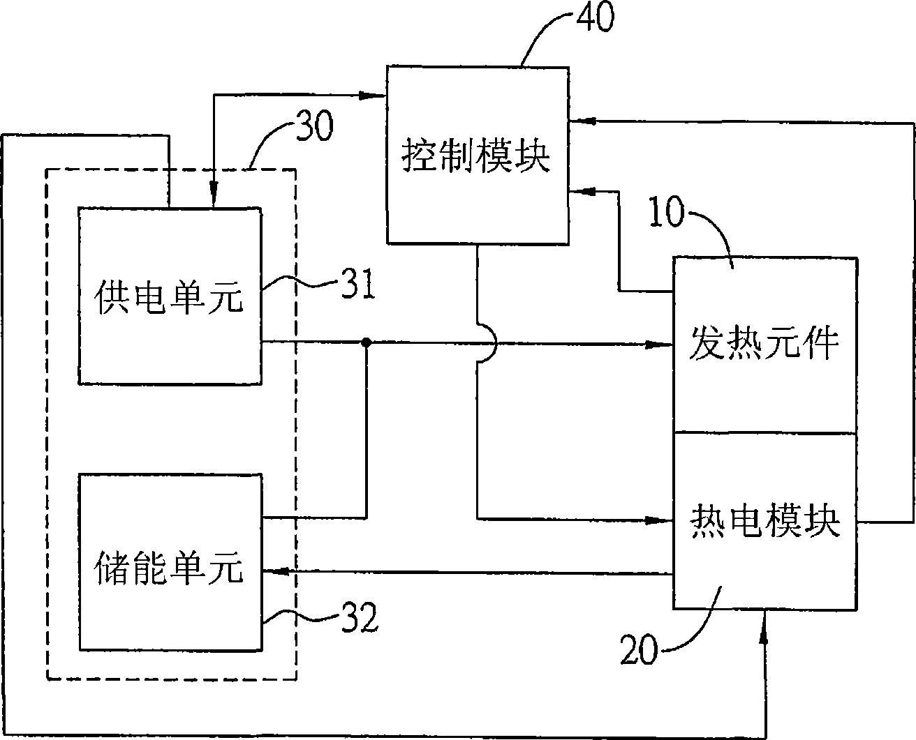
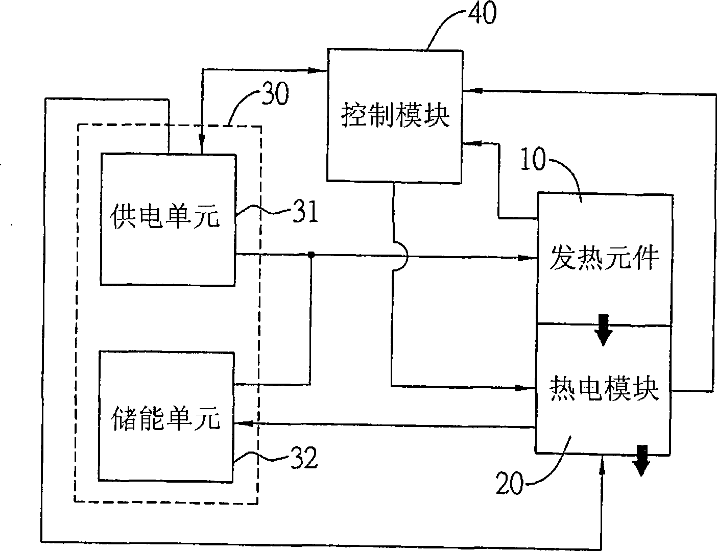
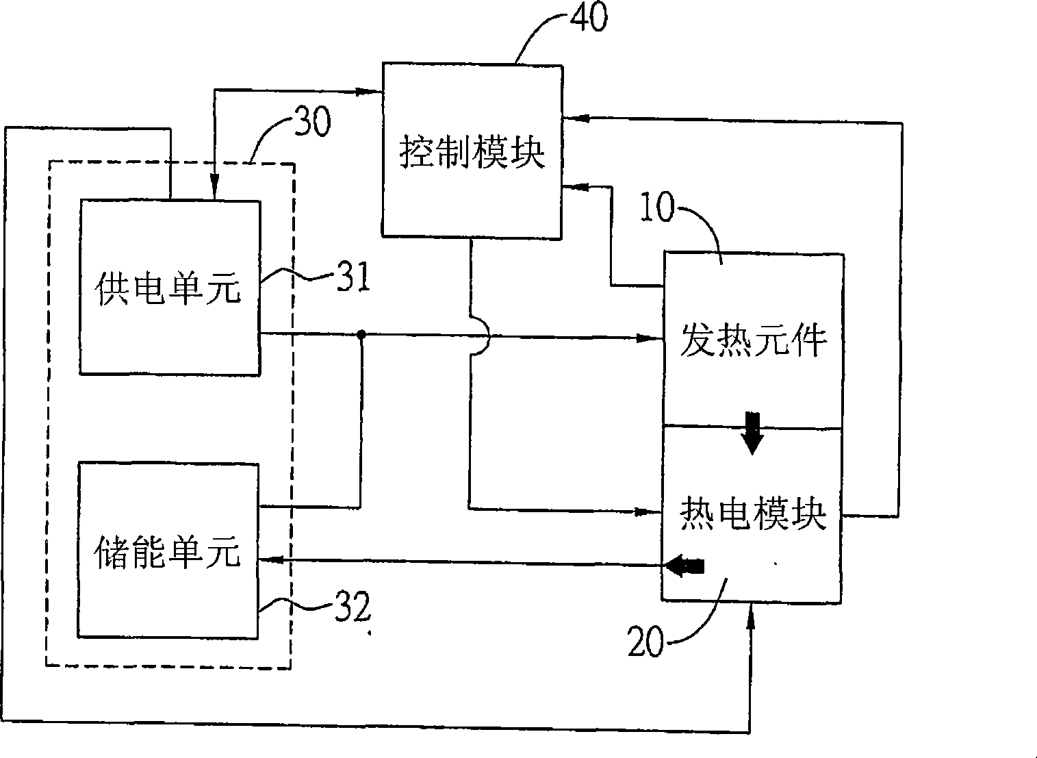
[0030] refer to figure 1 , is a schematic block diagram of the basic structure of a preferred embodiment of the heat dissipation control system of the present invention. As shown in the figure, the present invention is applied to cooling control of a heating element 10 . The he...


PUM


Abstract

The invention discloses a heat radiation control system and a heat radiation control method thereof, which is applied to cooling control of a heating element. By utilizing a thermoelectric module to mutually contact with the heating element and utilizing a control module to sense the temperature of the heating element, signals are sent to lead the thermoelectric module to cool the heating element when the heating element acts to lead the temperature of the heating element to increase to an preset temperature upper limit value, on the contrary, if the temperature of the heating element is lower than a preset lower limit value, heat generated by actions of the heating element is converted into electric power to be stored, thereby energy utilizing efficiency and heat radiation efficiency of the heating element can be increased relatively to prolong the service life of the heating element.

Description

technical field [0001] The present invention relates to a heat dissipation control system and a heat dissipation control method thereof, more specifically, to a heat dissipation control system and a heat dissipation control method applied to cooling heating elements. Background technique [0002] According to the light emitting mechanism of a general light emitting diode (Light Emitting Diode), it mainly relies on the combination of electron holes on the semiconductor P-N interface to excite light energy through the luminescent material. However, not every combination of electron holes can completely convert electrical energy into light. According to the photoelectric conversion efficiency of the current light-emitting elements, only about 40% can be converted into useful light sources, in other words, about 60% of the electric energy will be released as unusable heat energy. [0003] Because semiconductor materials (such as: ceramic materials) generally have excellent therm...

Claims


Application Information

Patent Timeline
Patent Type & Authority Applications(China)
IPC IPC(8): G05D23/19H05K7/20H01L23/34
Inventor 李崇华蔡宏杰
Owner AUROTEK CORP
Why Eureka
Try Eureka