Fuel cell system

A fuel cell system and fuel cell technology, applied in fuel cells, fuel cell additives, transportation fuel cell technology, etc., can solve problems such as inability to start the machine, poor startability, piping, and valve damage.

Inactive Publication Date: 2009-07-01
TOYOTA JIDOSHA KK
View PDF2 Cites 8 Cited by
  • Summary
  • Abstract
  • Description
  • Claims
  • Application Information

AI Technical Summary

Problems solved by technology

[0002] When the external temperature is low, there are problems that the water generated inside the fuel cell system freezes after the fuel cell system stops, and the piping, valves, etc. are damaged
In addition, in general, fuel cells are inferior to other power sources in terms of starting performance, especially at low temperatures, the desired voltage / current cannot be supplied, and the machine cannot be started.

Method used


Image

  • Fuel cell system
  • Fuel cell system
  • Fuel cell system

Examples


no. 1 approach

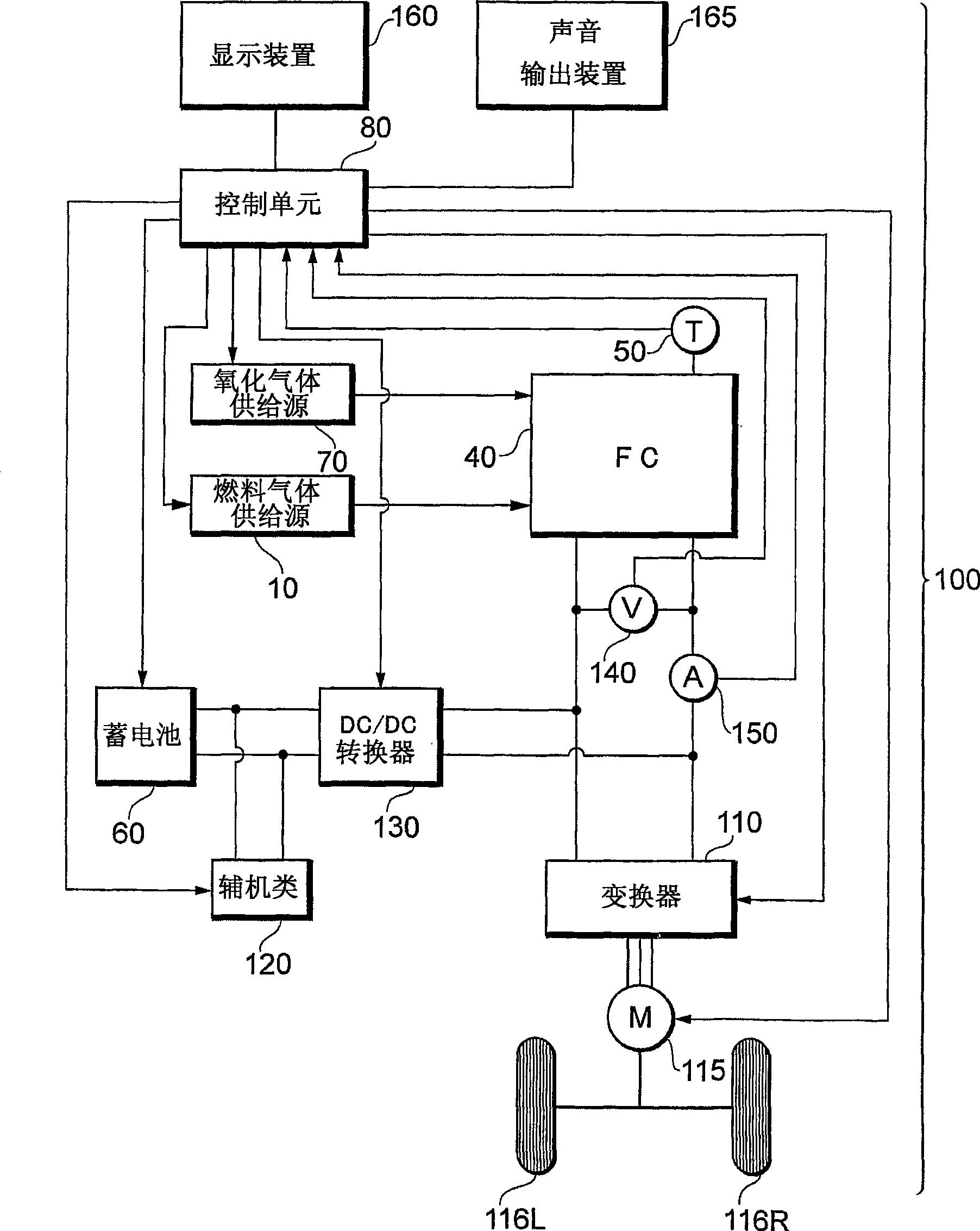
[0030] figure 1 It is a diagram showing the configuration of main parts of the fuel cell system 100 according to the first embodiment. In this embodiment, it is assumed that a fuel cell system mounted on a vehicle such as a fuel cell vehicle (FCHV: Fuel Cell Hybrid Vehicle), an electric vehicle, or a hybrid vehicle is applicable, but it can be applied not only to vehicles but also to various mobile bodies. (such as ships, aircraft, robots, etc.), fixed power supply.

[0031] The fuel cell 40 is a means for generating electric power from supplied reaction gases (fuel gas and oxidizing gas), and various types of fuel cells such as solid polymer type, phosphoric acid type, and molten carbonate type can be used. The fuel cell 40 has a stack structure in which a plurality of unit cells including MEAs and the like are stacked in series. The output voltage (hereinafter referred to as FC voltage) and output current (hereinafter referred to as FC current) of the fuel cell 40 are dete...

no. 2 approach

[0088] In the above-mentioned first embodiment, the case where the control for low temperature countermeasures is performed when the system is terminated is described, but there are also cases where control for low temperature countermeasures such as warm-up processing is required at the time of system startup, for example. Embodiments for realizing the control will be described below. In addition, since the hardware configuration of the fuel cell system according to the second embodiment is the same as that of the above-mentioned first embodiment, illustration and detailed description thereof will be omitted.

[0089] Figure 9 It is a flowchart showing activation processing according to this embodiment.

[0090] If the control unit 80 detects that the ignition switch is turned on, it will grasp the FC temperature T at that moment from the temperature sensor 50 f (step S310→step S320). Furthermore, the control unit 80 controls the preset allowable temperature T c (Tempera...

Deformed example 1

[0096] In the second embodiment, the change of FC temperature is shown, but it is also possible to change according to the FC temperature T f Calculate the amount of change to reach the allowable temperature T c The display device 160 and the voice output device 165 output the predetermined time (time related to the control for low-temperature countermeasures; hereinafter referred to as the Ready ON predetermined time) until now. Here, when displaying the scheduled Ready ON time, the number of seconds until the start of the normal operation may be displayed with numerical markers, or the elapsed time from the scheduled Ready ON time may be displayed with a bar graph. Here, the scheduled Ready ON time can be corrected step by step while calculating in real time, but it does not need to be corrected unless strict accuracy is required (for example, when the scheduled Ready ON time is displayed with a bar graph image, etc.). In addition, it is not necessarily necessary to report ...


PUM


Abstract

A fuel cell system capable of reporting that control for low-temperature countermeasure is performed without any strange feeling and false recognition of the user. When control for low-temperature such as scavenging at the system termination or warm-up at the system start-up is made, a text message or a speech message to the effect that the control will be performed is reliably presented or delivered to the user. Consequently, even in a situation where the system is operating after the ignition key is turned off, the user has neither strange feeling nor false recognition.

Description

technical field [0001] The invention relates to a fuel cell system. Background technique [0002] When the external temperature is low, there is a problem that water generated inside the fuel cell system freezes after the fuel cell system stops, and piping, valves, and the like are damaged. In addition, in general, fuel cells are inferior in startability compared to other power sources, and especially at low temperatures, there is a problem that a desired voltage / current cannot be supplied and equipment cannot be started. [0003] In view of such problems, the following proposals have been proposed: by performing scavenging treatment when the fuel cell system is stopped, the method of discharging the moisture retained inside the fuel cell to the outside (for example, refer to Patent Document 1); A method of preheating to improve the power generation efficiency of a fuel cell (for example, refer to Patent Document 2). [0004] Patent Document 1: Japanese Patent Laid-Open No...

Claims


Application Information

Patent Timeline
Patent Type & Authority Applications(China)
IPC IPC(8): H01M8/04H01M8/10B60L11/18
CPCY02T90/34H01M2250/20Y02T90/32B60L11/1894H01M8/04701Y02T10/7016H01M8/04589Y02E60/50H01M8/04559B60L11/1885B60L2250/30B60L11/1887H01M8/04253H01M8/04223H01M8/04753H01M8/04649H01M8/0432H01M8/04492B60L58/31B60L58/40B60L58/34Y02T10/70Y02T90/40H01M8/04225H01M8/04
Inventor 真锅晃太繁雅裕野野部康宏
Owner TOYOTA JIDOSHA KK
Why Eureka
Try Eureka