
Cutter knife and knife head equipped with same

A blade and blade technology, used in grain processing and other directions, can solve problems such as labor and material loss, reduce energy consumption, simplify manufacturing processes, and prevent excessive regrinding.

Inactive Publication Date: 2009-07-08
GW斯特芬斯有限责任两合公司
View PDF2 Cites 6 Cited by
  • Summary
  • Abstract
  • Description
  • Claims
  • Application Information

AI Technical Summary

Problems solved by technology

This regrinding involves considerable material loss and is labor intensive

Method used


Image

  • Cutter knife and knife head equipped with same
  • Cutter knife and knife head equipped with same
  • Cutter knife and knife head equipped with same

Examples


Embodiment Construction

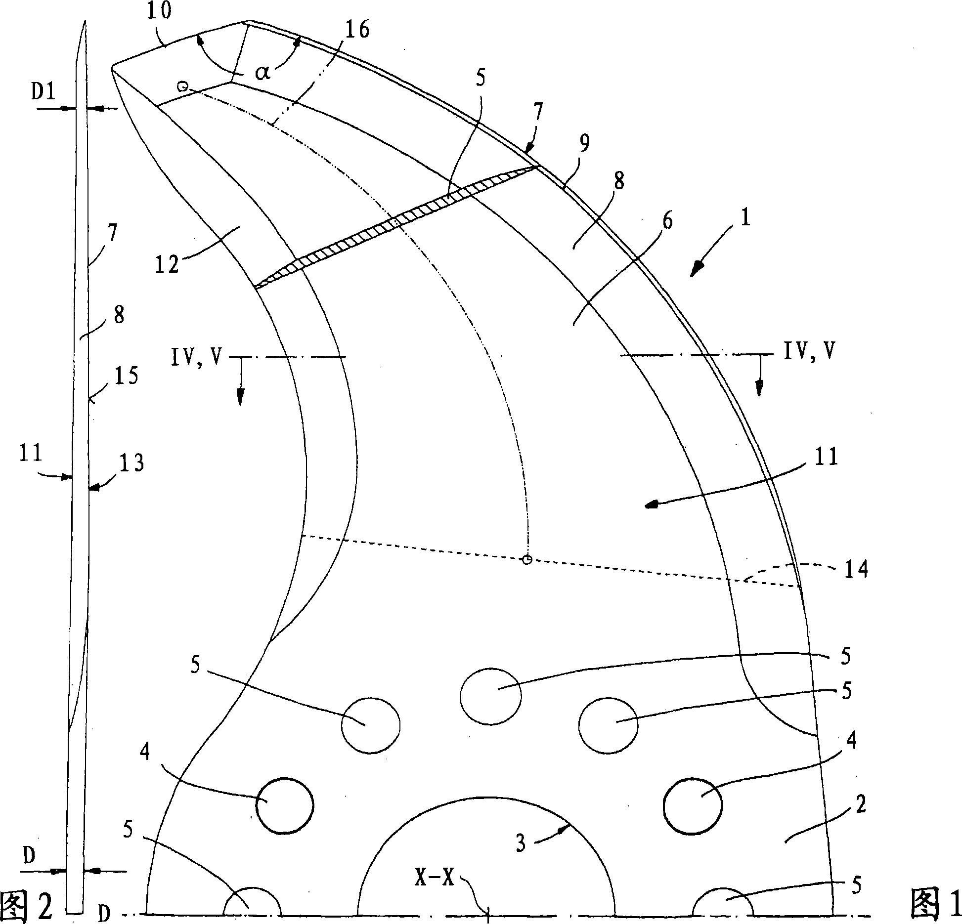
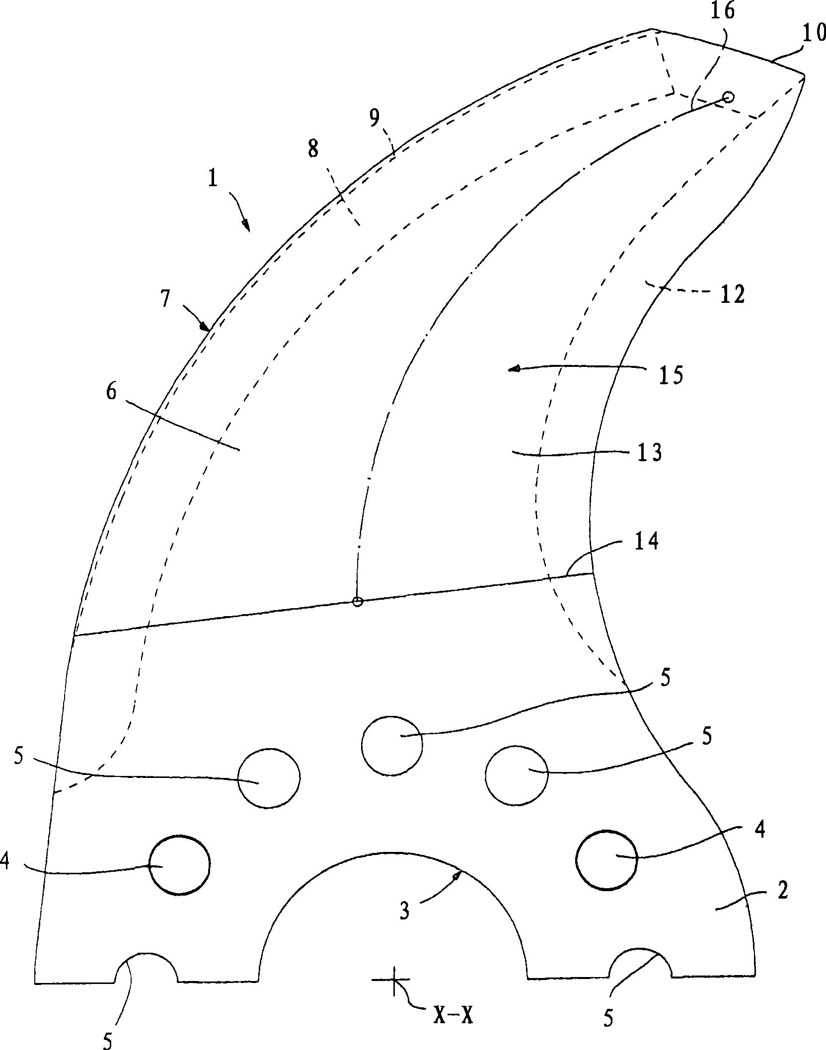
[0037]The chopping knife 1 comprises a semicircular clamping part 2 with a central hole 3 with an axis of rotation X-X, two centering holes 4 for inserting on a centering pin not shown in the figure and through holes 5. Stretch out sickle-shaped blade 6 from clamping part 2, blade outer side is a part circular arc blade 7, and blade inner side has wider blade facet 8 and outer side has narrower blade facet 9. Immediately following the outer extremity of the cutting edge 7 is a relatively blunt emulsified edge 10 with an obtuse angle α. On the same first side 11 where the blade 6 is visible, there is a relatively blunt curved back edge 12 .

[0038] The chopping knife 1 extends in principle perpendicular to the axis of rotation X-X. The first side 11 of the blade 6 is in the same plane as the visible face of the clamping part 2 shown in FIG. 1 . The clamping portion 2 and the beginning of the blade 6 have the same thickness D (see FIG. 2 ). On the second side 13 (see attach...


PUM


Abstract

The invention relates to a chopping knife (1) which is rotationally supported around an axial line (X-X) by an at least partially arced flat fixed part (2) and comprises a reaphook-shaped blade (6) having a cutting edge (7) of which the outer side is arced and knife back edge face (12) of which the inner side is arced. Thickness (D) of the blade is reduced outwards along the redial direction. Arris faces (8, 9) of the cutting edge (7) and the knife back edge face (12) are on the same first side (11) of the blade (6). The thickness (D) of the blade (6) is reduced through an inclined plane (15) extending on a second side (13).

Description

technical field [0001] The invention relates to a chopping knife and a knife head comprising at least one such chopping knife. Background technique [0002] A chopping knife for chopping and mixing meat, sausage mince or sausage stuffing or similar food (hereinafter referred to as substance) in a chopping machine, especially in various forms and sizes used in the meat processing industry chopping knife. Usually a plurality of chopping knives are fixed on the drive shaft side by side in the axial direction, or they are distributed around the drive shaft and fixed in the same plane to form a so-called cutter head, as in the applicant's patent document DE37 32 237 C1 mentioned. The main function of the chopping knife is to chop the material in the chopping machine into a certain desired size and mix it. This process should be done as quickly, energy-efficiently, and as thoroughly as possible, without overheating the substance. Chopping knives must be able to withstand enorm...

Claims


Application Information

Patent Timeline
Patent Type & Authority Applications(China)
IPC IPC(8): B02C18/20B02C18/16
CPCB02C18/20
Inventor M·斯特芬斯
Owner GW斯特芬斯有限责任两合公司
Learn More