Vertical lathe workstation control system

A control system and vertical lathe technology, applied in the field of control systems, can solve the problems of low precision machining of workpieces, slow running speed, large maintenance amount, etc., and achieve the effects of stable power supply process, stable speed change, and guaranteed machining accuracy.

Inactive Publication Date: 2009-07-08
SHENYANG LIGONG UNIV
View PDF0 Cites 5 Cited by
  • Summary
  • Abstract
  • Description
  • Claims
  • Application Information

AI Technical Summary

Problems solved by technology

However, with the improvement of the technical level, these traditional control methods are increasingly showing its shortcomings and deficiencies, such as high energy consumption, high failure rate, large maintenance amount, long maintenance cycle, complicated speed regulation methods, and

Method used


Image

  • Vertical lathe workstation control system
  • Vertical lathe workstation control system
  • Vertical lathe workstation control system

Examples


Embodiment

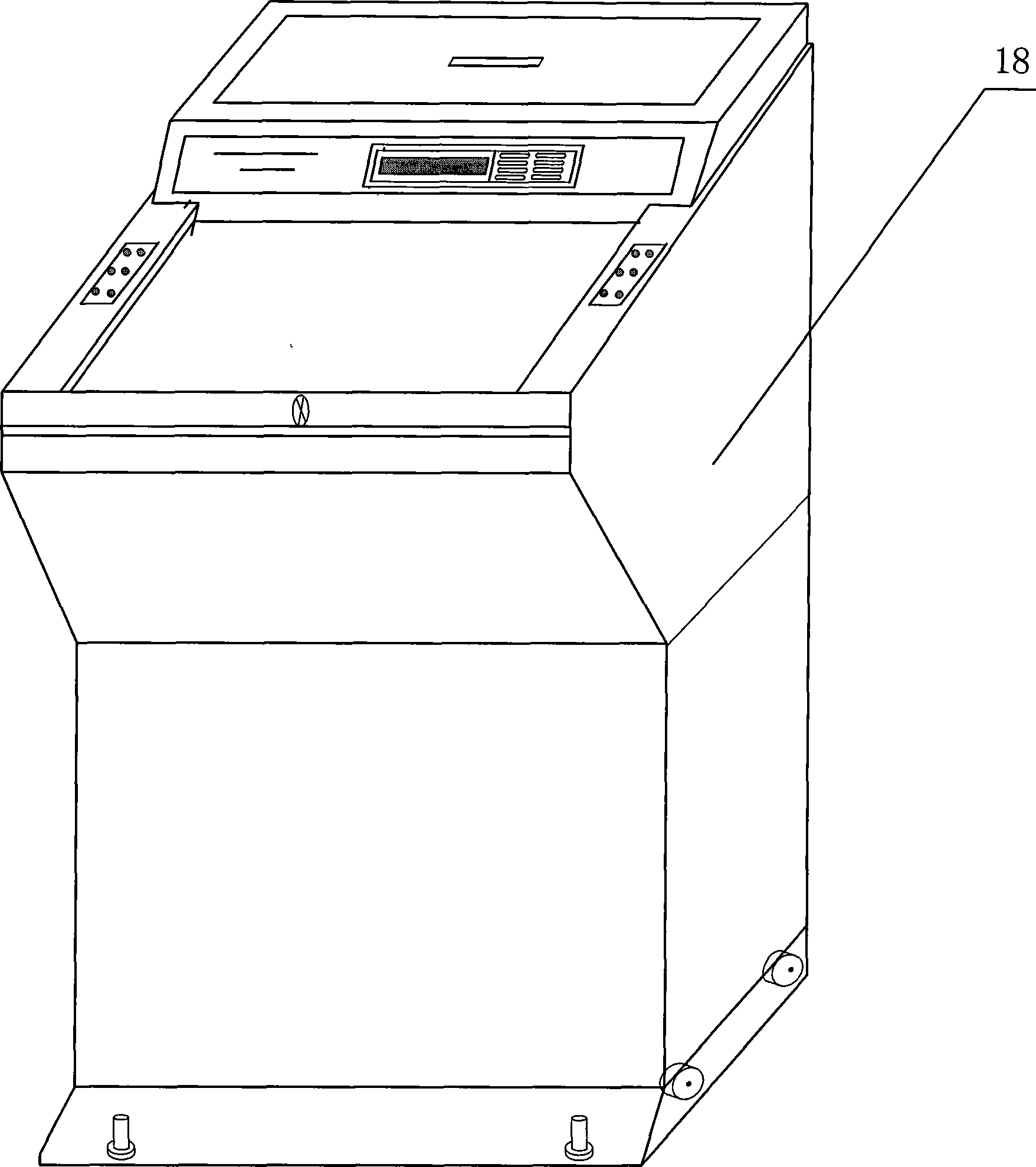
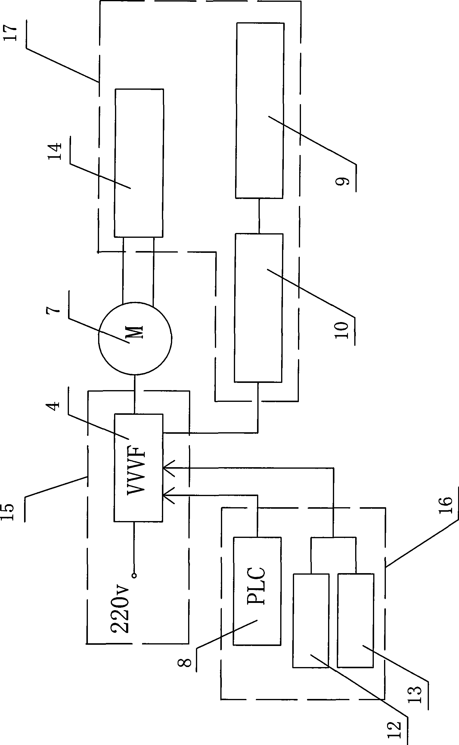
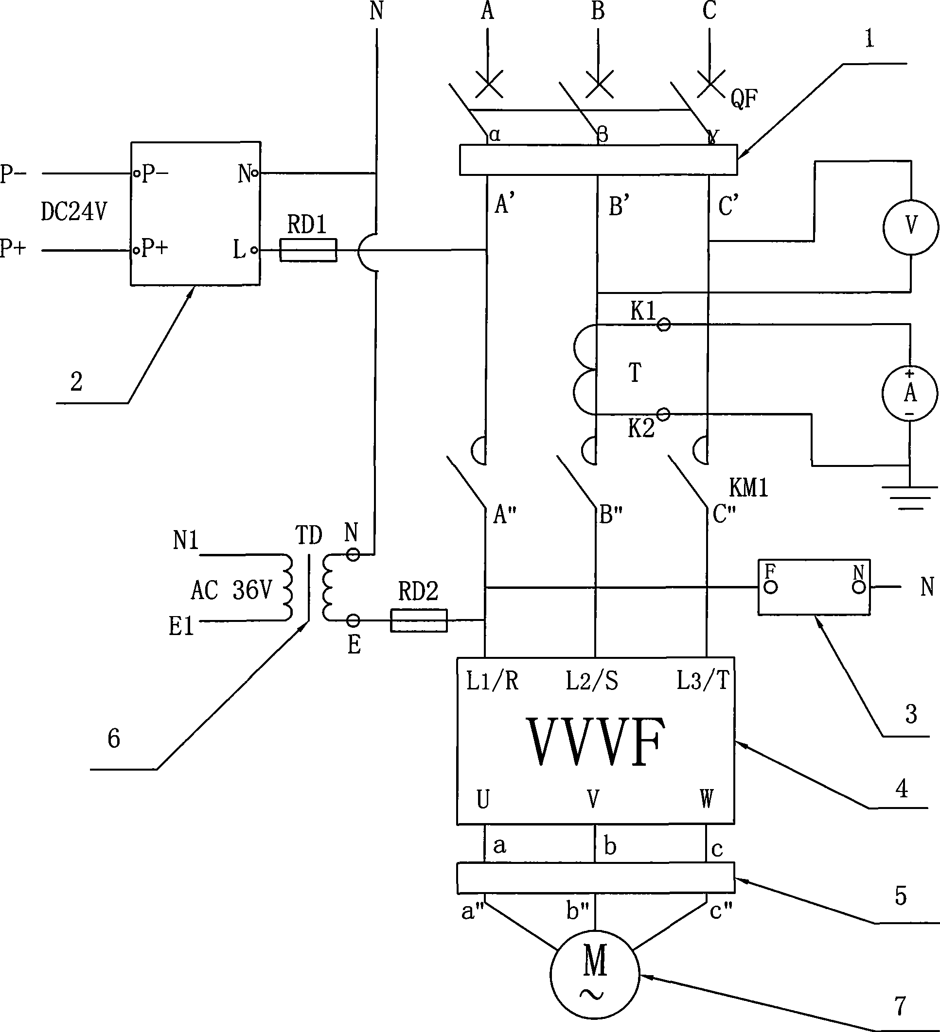
[0049] A vertical lathe table control system, such as figure 1 and 2 As shown, it includes a cabinet body 18 and a main circuit 15 installed in the cabinet body 18, an auxiliary control circuit 16 and a braking unit 17, and the main circuit 15, such as image 3 As shown, it includes combination switch QF, input power filter 1, AC contactor KM1, frequency converter VVVF4 and output power filter 5; the volume of cabinet 18 is 1600mm×2000mm×600mm; the frequency converter VVVF4 is selected with torque vector The general-purpose frequency converter controlled by Japan Fuji is the model FRN55G11S-4CX frequency converter.

[0050] The main circuit 15 is AC A, B, C three-phase four-wire respectively connected to the lead-in end of the combination switch QF, and the lead-out end of the combination switch QF is connected to the input terminal α, β, γ of the input power filter 1 correspondingly, and the input The output terminals A`, B`, C` of the power filter 1 are connected to the in...


PUM


Abstract

A vertical lathe worktable control system comprises a cabinet body, a main circuit, an auxiliary control circuit and a braking circuit, wherein the main circuit, the auxiliary control circuit and the braking circuit are installed in the cabinet body. In the main circuit, alternating-current three-phase four-wire is connected with a power source input end of transducer VVVF through a combination switch QF, an input power source filter and an alternating-current contactor KM1. The output of main circuit is connected with a main electric motor through an output power source filter. A PLC programmable controller is the core of auxiliary control circuit. A braking unit comprises a transducer braking mechanism, a braking resistor box, a first transducer frequency setting potentiometer, a second transducer frequency setting potentiometer, a second transducer inching frequency setting potentiometer, a transducer frequency meter and an electromagnetic brake. The transducer VVVF is connected with the transducer braking mechanism. The vertical lathe worktable control system of the invention has the advantages of simple structure, strong reliability, convenient speed adjustment, energy consumption saving, increased operation speed and increased cutting efficiency. The vertical lathe worktable control system of the invention can be widely used on the cutting mechanical device.

Description

technical field [0001] The invention relates to a control system, in particular to a vertical lathe workbench control system. Background technique [0002] At present, most of the control methods of the vertical lathe worktable are driven by the DC generator set to rotate the DC motor, and the rotation number is set through the speed regulating resistor of the auxiliary control circuit, and some use the thyristor DC governor to directly adjust the rotation of the DC motor. The conduction angle of the silicon controlled rectifier is realized by the auxiliary control circuit, that is, the silicon controlled silicon trigger circuit. However, with the improvement of the technical level, these traditional control methods are increasingly showing its shortcomings and deficiencies, such as high energy consumption, high failure rate, large maintenance amount, long maintenance cycle, complicated speed regulation methods, and high-order harmonics generated It interferes with the powe...

Claims


Application Information

Patent Timeline
IPC IPC(8): B23Q15/00H02J3/01G05B19/18
CPCY02E40/40Y02P70/10
Inventor 石征锦王耀成
Owner SHENYANG LIGONG UNIV
Why Eureka
Try Eureka