Eureka AIR delivers breakthrough ideas for toughest innovation challenges, trusted by R&D personnel around the world.

Auxiliary tool changing device of drum type chipper

A tool changing device and chipper technology, which is applied in the manufacture of thin wood chips, wood processing equipment, manufacturing tools, etc., can solve the problems of long replacement of flying knives, high labor intensity of workers, and reduced production efficiency, etc., and achieve labor intensity The effect of reducing, prolonging production time and improving production efficiency

Active Publication Date: 2009-07-08
江苏保龙机电制造有限公司
View PDF0 Cites 10 Cited by
  • Summary
  • Abstract
  • Description
  • Claims
  • Application Information

AI Technical Summary

Problems solved by technology

Due to the heavy weight of the cutter roller, for example, the weight of the cutter roller of a large-scale drum chipper reaches about 8.5 tons. When replacing the flying knife, several adults are needed to complete the rotation of the cutter roller. The current drum chipper assists the tool change The device has the following defects: (1), time-consuming and labor-intensive, the replacement time is long, and it takes a long time to replace the flying knives because it takes a long time to rotate the knife rollers, so it generally takes about an hour to replace all the flying knives on the drum chipper time, and the labor intensity of workers is high, which consumes a lot of manpower, resulting in a waste of human resources; (2), greatly reducing production efficiency
It is necessary to stop the operation when replacing the flying knife, and the production cannot be carried out. Due to the long time for changing the flying knife, this greatly reduces the production efficiency

Method used


Image

  • Auxiliary tool changing device of drum type chipper
  • Auxiliary tool changing device of drum type chipper
  • Auxiliary tool changing device of drum type chipper

Examples


Embodiment

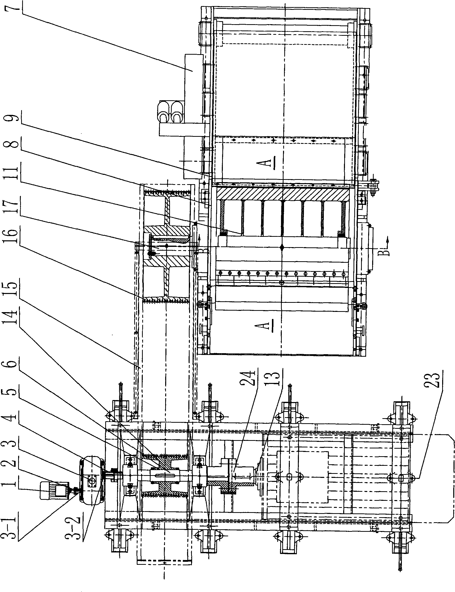
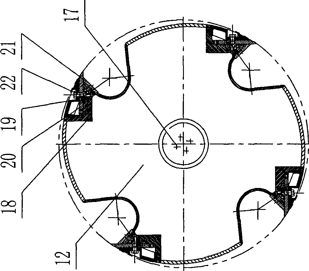
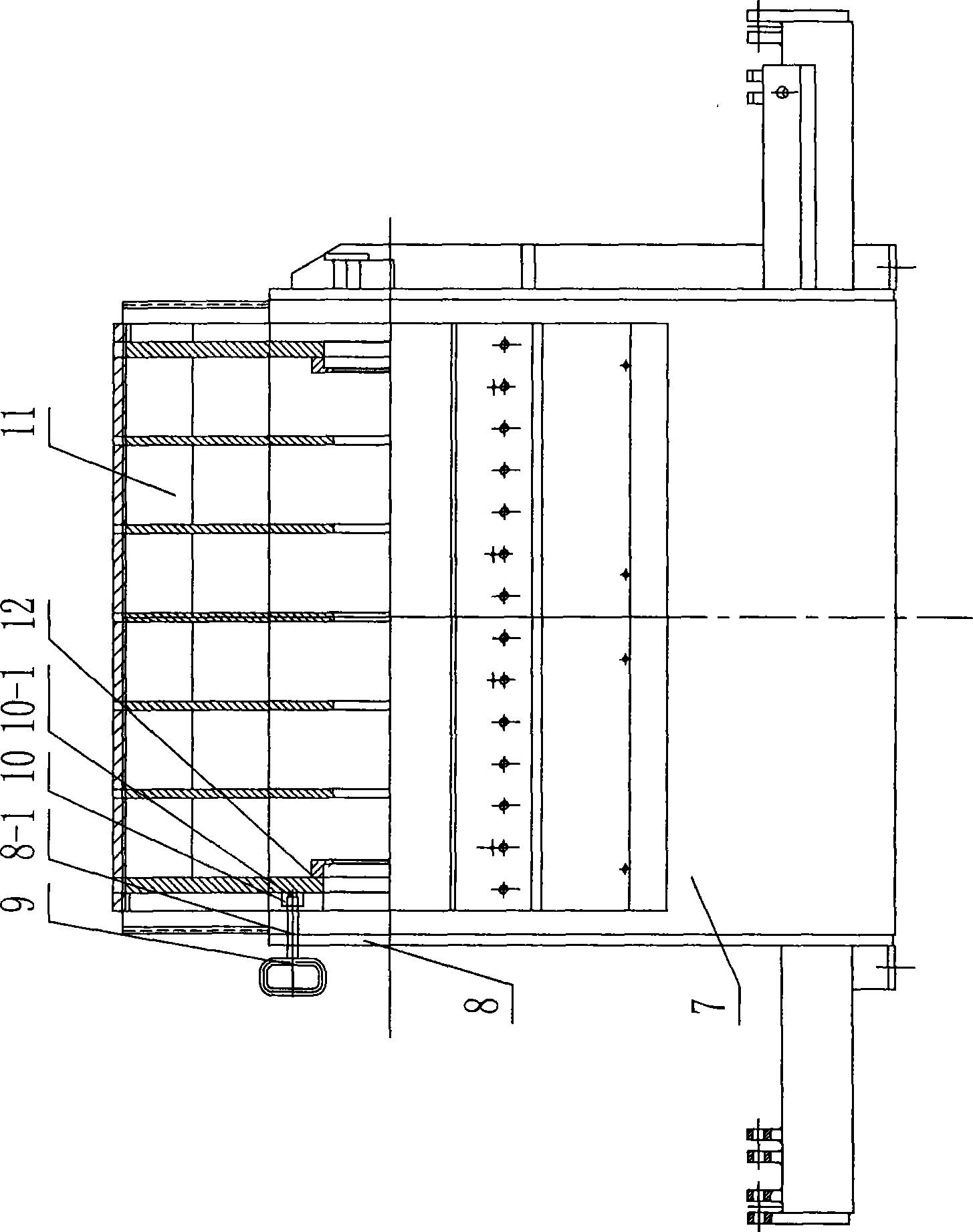
[0016] Such as Figure 1 to Figure 5 As shown, an auxiliary tool change device for a drum chipper includes a pin 9, four positioning blocks 10, a frame hole 8-1, an auxiliary tool change motor 1, a coupling 2, A speed reducer 3, an electromagnetic clutch 4, the positioning block 10 is arranged on the lining plate 12 of the end face of the knife roller 11, a positioning hole 10-1 is opened on each positioning block 10, and the frame hole 8-1 is opened in the drum type On the base side plate 8 of the chipper base 7. The pin 9 is arranged on the frame side plate 8 of the drum chipper frame 7, the reducer 3 has an input shaft 3-1 and an output shaft 3-2, the auxiliary tool change motor 1 is an AC motor, and the auxiliary tool change The motor 1 is connected to the input shaft 3-1 of the reducer 3 through a coupling 2, and the electromagnetic clutch 4 is arranged between the output shaft 3-2 of the reducer 3 and the main shaft 6 of the drum chipper driving device 5. The structure...


PUM


Abstract

The present invention relates to a drum chipper, and particularly relates to an auxiliary cutter changing device of drum chipper. The auxiliary cutter changing device of drum chipper comprises an inserted pin (9), a positioning block (10) and a chipper base hole (8-1). The positioning block (10) is installed on a lining board (12) at the end plane of cutter roller (11). A positioning hole (10-1) is provided on the positioning block (10). The chipper base hole (8-1) is installed on a chipper base side plate (8). The auxiliary cutter changing device of drum chipper also comprises an auxiliary cutter changing motor (1), a coupling (2), a speed reducer (3) and an electromagnetic clutch (4). The auxiliary cutter changing motor (1) is connected with an input shaft (3-1) of speed reducer (3) through the coupling (2). The electromagnetic clutch (4) is installed between the output shaft (3-2) of speed reducer (3) and a main shaft (6) of drum chipper driving device (5). The auxiliary cutter changing device of drum chipper according to the invention has the advantages of: (1) time saving, labor saving, and short changing time; (2) greatly increased production efficiency.

Description

technical field [0001] The invention relates to a drum chipper, in particular to an auxiliary tool changing device for a drum chipper. Background technique [0002] The drum chipper is based on wood harvesting residues (such as small-diameter wood, technical branches, etc.), wood processing residues (such as slabs, slats, round wood cores, waste veneers, etc.) and non-wood raw materials (such as bamboo) , straw, wheat straw, cotton stalks, etc.) as cutting raw materials, cutting and processing raw materials into wood or non-wood chips of certain specifications, drum chippers can be used as materials preparation machinery for MDF, particle board, papermaking and other industries , It can also be used as a direct production equipment for finished wood chips. When the drum chipper is working, the working motor in the driving device of the drum chipper starts, and through the belt drive, the shaft fixed to the large pulley rotates, so that the knife roller fixed on the shaft ro...

Claims


Application Information

Patent Timeline
Patent Type & Authority Applications(China)
IPC IPC(8): B27L5/00
Inventor 周水保圣爱兵
Owner 江苏保龙机电制造有限公司
Why Eureka
Eureka Blog
Learn More