
On-site detecting instrument for foundation bearing capacity and filling compactness

A technology of foundation bearing capacity and compactness, which is applied in the field of foundation soil survey, foundation structure engineering, foundation structure test, etc. major problems, to achieve considerable social benefits, save manpower and material resources, and avoid visual errors.

Active Publication Date: 2011-05-25
SHENYANG JIANKE INSTR ACADEME
View PDF1 Cites 3 Cited by
  • Summary
  • Abstract
  • Description
  • Claims
  • Application Information

AI Technical Summary

Problems solved by technology

Its shortcomings are: the error increases after the spring is fatigued, and because the probe is only 1cm long, the sounding depth is limited and cannot be tested in situ on site, and the soil sample must be taken out by drilling, which increases the disturbance and dehydration of the soil
Its shortcomings are: the visual error of the scale display itself exceeds ±5%, the error increases after the spring is used as the force measuring element, and the data disappears after the scale shrinks and cannot be retained.
Its disadvantage is: since the gamma ray source has cobalt 60 (CO 60 ) and Cesium 137 (CS 137 ) composition, radiation to the human body and pollution to the environment are well known, so its protection, radiation protection, special care, and safety facilities are very complicated
Its shortcomings: labor-intensive, time-consuming, costly and laborious

Method used


Image

  • On-site detecting instrument for foundation bearing capacity and filling compactness
  • On-site detecting instrument for foundation bearing capacity and filling compactness

Examples


Embodiment Construction

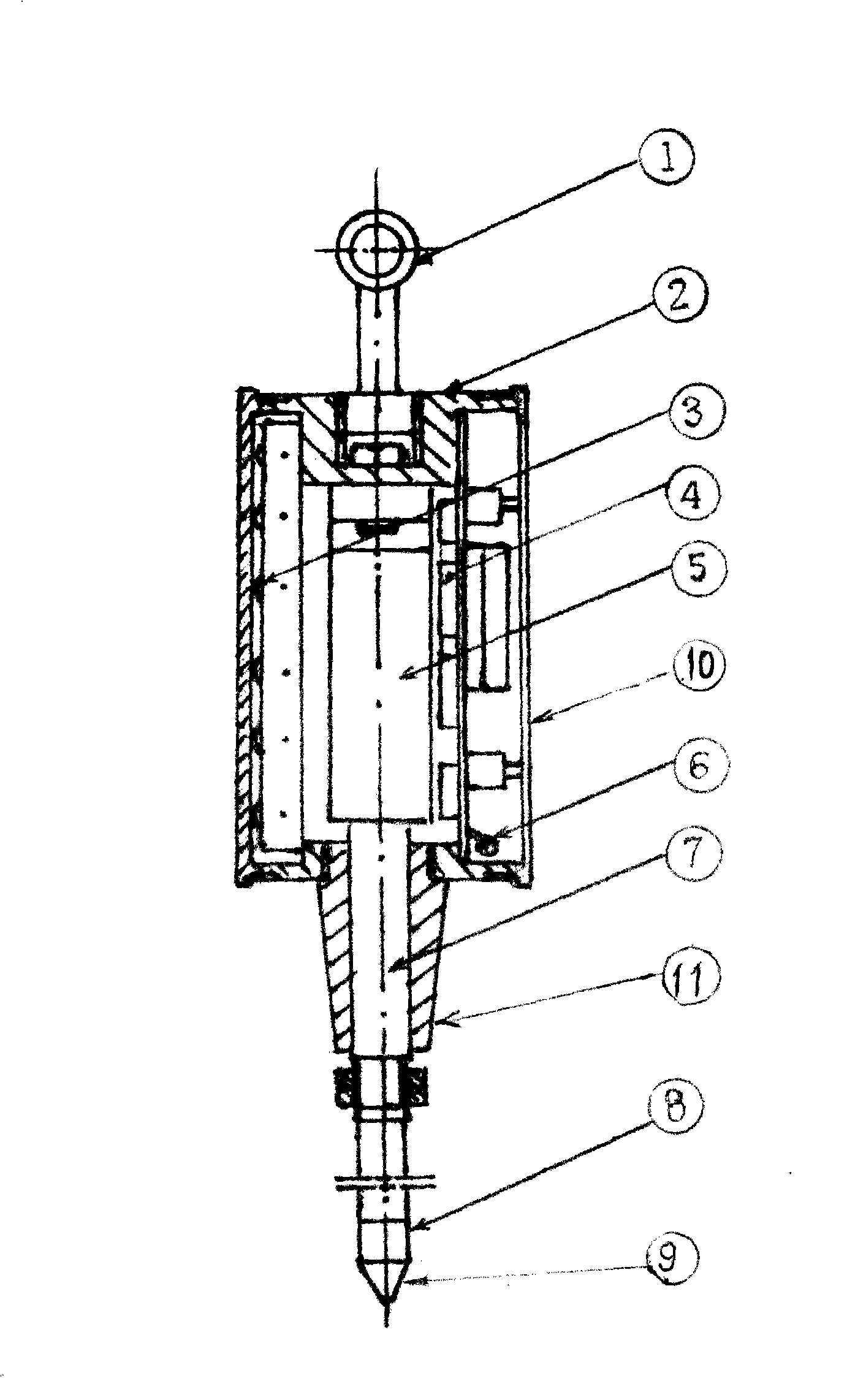
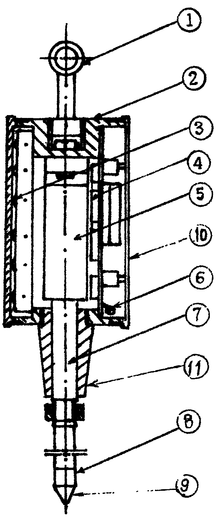
[0010] Fig. 1 is an embodiment of this design scheme: a special casing 2 systematically combines the load sensor 5-mechanical transmission system (transmission shaft 7, probe rod 8, probe 9)-data acquisition processor 4 , its features: the top of the casing 2 is provided with a T-shaped beam 1, the center of the inner cavity of the casing 2 is fixed with a load sensor 5, the bottom of the casing 2 is equipped with a displacement guide sleeve 11, and the casing 2 is equipped with a data acquisition device. The processor 4, the power supply box 3, and the casing 2 are equipped with a control display panel 10 and a communication interface 6. The load sensor 5 is connected with the transmission shaft 7, and then connected with the probe rod 8 and the probe 9 in turn.

[0011] The penetrating rod 8 in Fig. 1 is designed as a single-section or multi-section structure according to the detection requirements, and the sections are connected by threads, keyways, and nails. The surface o...


PUM


Abstract

The invention relates to a foundation bearing capacity filling packing in-situ detector, belonging to the geotechnical engineering mechanics field. which comprises: a casing, a crossbeam, a load sensor, a transmission shaft, a sounding rod, a sounding head, a data acquisition processor, a control display panel, a communication interface and a power supply box; The invention is characterized in that: the transmission shaft, the sounding rod and the sounding head is connected with the bottom of the load sensor fixed in the inner cavity of the casing; when the sounding head is inserted into soilmass, the load sensor generates a changeable signal, the signal is sampled, amplified, calculated and displayed by the data acquisition processor, and sent to the upper machine through the communication interface for intelligentizing processing. The invention is distinguished from the penetration test apparatus, sand cone method and nucleon density apparatus used in current engineerings, can solves the following problems in existing technologies: 1, in-situ disturbing dehydration caused by drilling soil sampling, 2, radiation pollution of the nucleon density apparatus, 3, the time and labor consumed in digging pit and filling sand, 4, large error in spring force measuring element, 5, visual error in rule read value and impossibility for keeping data.

Description

Technical field: [0001] An on-site tester for foundation bearing capacity filling density involves fields such as geotechnical engineering survey, design, construction, etc. Mechanics index. Background technique: [0002] In the practice of geotechnical engineering, we often come into contact with natural foundations and artificial backfill foundations. For the evaluation of particle size, density distribution arrangement, load strength, and water content of such soils, the judgment of critical state and limit state indicators , will directly affect and control the quality of construction projects, and is a century-old plan for national capital construction. Therefore, it is very important to carry out on-site quantitative testing and qualitative analysis of the filling density of the foundation bearing capacity. [0003] Among the existing related technologies are A: "Electronic micro-penetrator" refer to Chinese patent: 88216921.1 - produced by Shenyang Institute of Autom...

Claims


Application Information

Patent Timeline
Patent Type & Authority Patents(China)
IPC IPC(8): E02D1/02
CPCE02D1/022E02D33/00
Inventor 不公告发明人
Owner SHENYANG JIANKE INSTR ACADEME
Learn More