

Back light module and liquid crystal display
A technology of backlight module and light beam, which is applied in the direction of static indicators, semiconductor devices of light-emitting elements, instruments, etc., can solve the remaining 45% of the problems, and achieve the effect of improving the overall brightness and increasing the utilization rate of photons
- Summary
- Abstract
- Description
- Claims
- Application Information
AI Technical Summary
Problems solved by technology
Method used
Image

Examples
no. 1 example
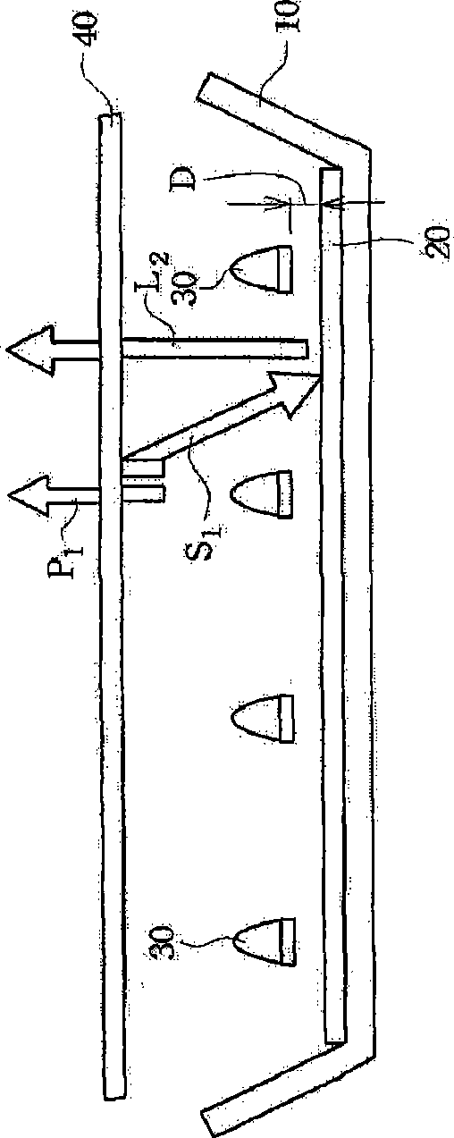
[0048] Please refer to Figure 1A , which shows a schematic structural view of the first embodiment of the backlight module according to the present invention. The backlight module of this embodiment includes: a reflective base 10 , a red fluorescent material layer 20 , a plurality of LED assemblies 30 and an optical film 40 .
[0049] The red fluorescent material layer 20 is disposed on the bottom surface or the side surface of the reflective base 10, and the LED assembly 30 is disposed above the reflective base 10 and the red fluorescent material layer 20, and can emit a first light beam P 1 +S 1 ; Wherein, the light-emitting diode assembly 30 is composed of blue light-emitting diodes and green light-emitting diodes, or blue light-emitting diodes and green phosphors, so as to generate blue light and green light, the first light beam P 1 +S 1The wavelength range is between 420 nanometers (nm) and 580 nanometers (nm). The optical film 40 is disposed above the reflection ba...
no. 2 example
[0054] Please refer to Figure 2A , which shows a schematic structural view of the second embodiment of the backlight module according to the present invention. The backlight module of this embodiment includes: a reflective base 10 , a fluorescent material layer 22 including red fluorescent materials and green fluorescent materials, a plurality of LED components 32 and an optical film 42 .
[0055] The fluorescent material layer 22 is disposed on the bottom surface or the side surface of the reflective base 10, and the LED assembly 32 is disposed above the reflective base 10 and the fluorescent material layer 22, and can emit a first light beam P 1 +S 1 ; Wherein, the light-emitting diode assembly 32 is made up of blue light-emitting diodes, the first light beam P 1 +S 1 The wavelength range is between 420 nanometers (nm) and 500 nanometers (nm). The optical film 42 is disposed above the reflection base 10 , the fluorescent material layer 22 and the LED assembly 32 . Ther...
no. 3 example
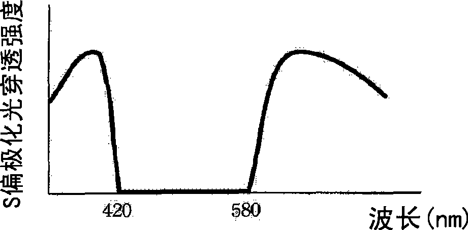
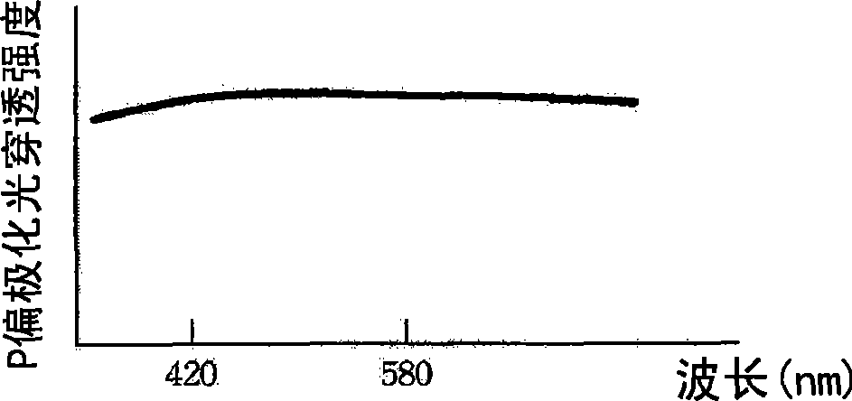
[0059] Please refer to image 3 , which shows a schematic structural view of the third embodiment of the backlight module according to the present invention. In this embodiment, the yellow fluorescent material layer 24 is used to replace the fluorescent material layer (red and green fluorescent materials) 22 of the second embodiment of the present invention, and the reflected S polarized light S 1 The wavelength range is also between 420 nanometers (nm) and 500 nanometers (nm), and the arrangement and characteristics of other components are the same as those of the second embodiment, please refer to the second embodiment of the present invention, and will not repeat them here.
[0060] The first light beam P of the first, second and third embodiments of the invention 1 +S 1 Both contain blue light with the strongest wavelength range between 440 nanometers (nm) and 490 nanometers (nm).
[0061] Various embodiments of the present invention are described below, which adjust or...
PUM
| Property | Measurement | Unit |
|---|---|---|
| Thickness | aaaaa | aaaaa |
| Thickness | aaaaa | aaaaa |
| Thickness | aaaaa | aaaaa |
Abstract
Description
Claims
Application Information