Plasma flat-plate light source

A flat light source, plasma technology, applied in the direction of gas plasma lamps, etc., to achieve the effect of increasing luminous efficiency, improving luminous efficiency and brightness

Inactive Publication Date: 2009-07-08
SOUTHEAST UNIV
View PDF0 Cites 0 Cited by
  • Summary
  • Abstract
  • Description
  • Claims
  • Application Information

AI Technical Summary

Problems solved by technology

[0003] The object of the present invention is to propose a low-frequency square wave drive mode for the negative glow region discharge mode in the existing plasma flat light source working mode, so that the plasma flat light source can produce a positive column discharge working mode, and improve luminous efficiency and luminous brightness at the same time

Method used


Image

  • Plasma flat-plate light source
  • Plasma flat-plate light source
  • Plasma flat-plate light source

Examples


Embodiment 1

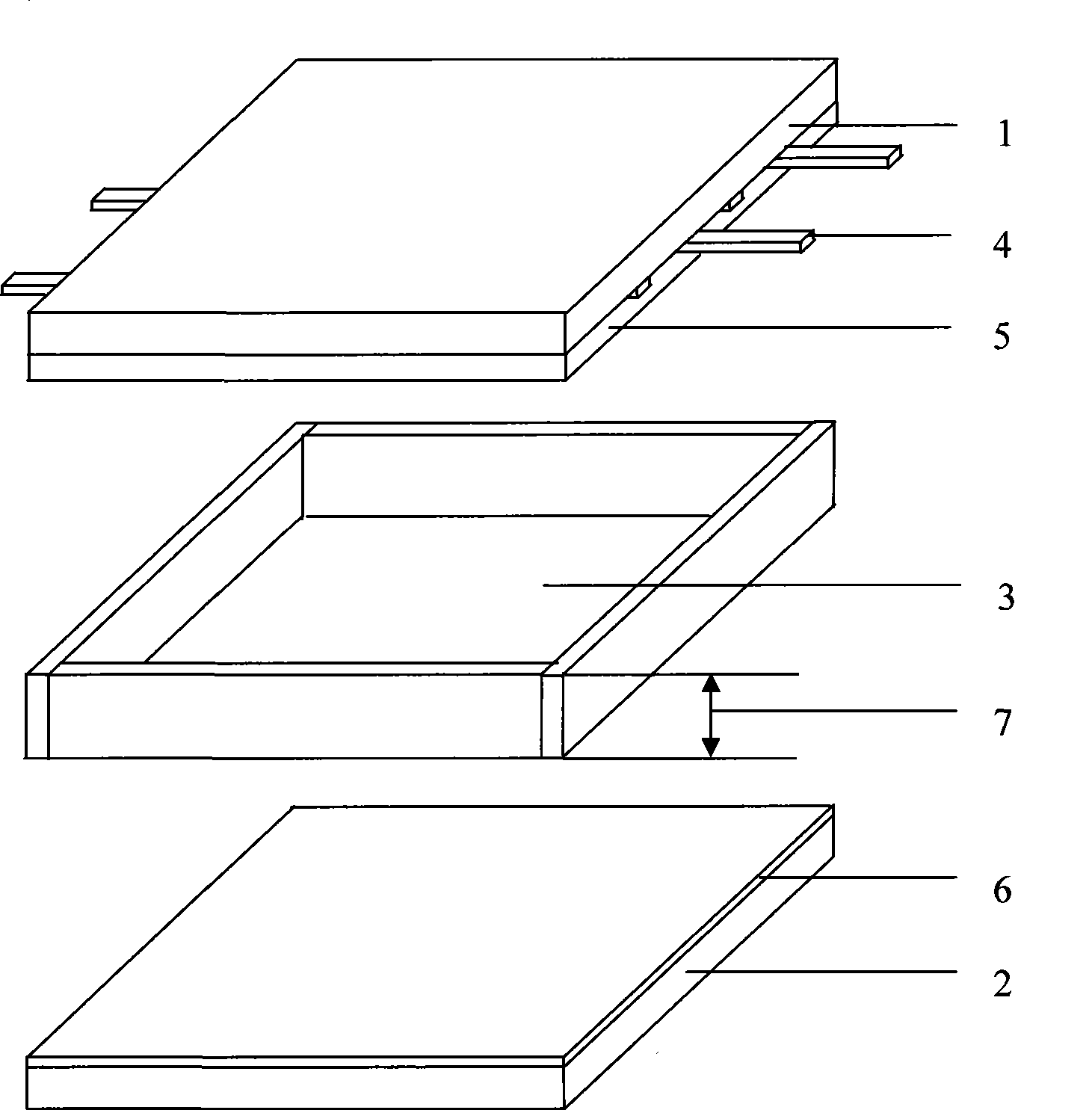
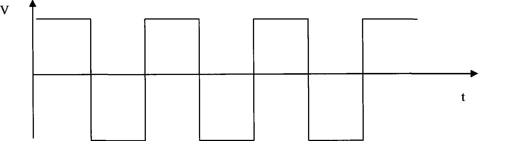
[0021] Embodiment 1, the structure of the plasma flat panel light source adopting the new discharge mode is as follows figure 1 As shown, it includes a front substrate 1 and a rear substrate 2, a discharge chamber 3 is provided between the front substrate and the rear substrate, parallel electrodes 4 are arranged on the front substrate, and the electrode spacing is 3 mm to 10 mm, and the electrode layer is covered with a transparent medium layer and Protective film 5, the rear substrate is coated with a mixed layer 6 of three-color phosphors to emit white light, the distance 7 between the front and rear substrates is 0.7 mm to 1.5 mm, and the working gas filled in the discharge cavity is a mixed gas of Ne and Xe gases, of which The proportion of Xe is equal to 20%, and the pressure of the working gas is 400-700 Torr. A low-frequency square wave trigger driving waveform such as figure 2 As shown, the above-mentioned plasma flat panel light source is driven to obtain the worki...

Embodiment 2

[0023] Embodiment 2, the structure of the plasma flat panel light source adopting the new discharge mode is as follows figure 1 As shown, the parallel electrodes on the front substrate 1 are electrodes 9 with planar protrusions, such as Figure 5 As shown, other conditions remain unchanged, when the low-frequency square wave is triggered to drive the plasma flat panel light source, the working mode of positive column discharge is also obtained, and the working principle is the same as that of the first embodiment.

Embodiment 3

[0024] Embodiment 3, when the Xe ratio is higher than 20%, up to 100% pure Xe gas, under the drive of low frequency square wave, the working mode of positive column discharge is also obtained, but the optimal frequency varies with the Xe ratio. The working principle is the same as that of Embodiment 1, and constitutes a group of embodiments.


PUM


Abstract

A plasma flat light source relates to the technical field of plasma flat light sources, in particular to the technical field of a low-frequency drive pattern of a plasma flat light source. The plasma flat light source comprises a front base plate, a rear base plate and an electric discharge cavity, wherein, the electric discharge cavity is arranged between the front base plate and the rear base plate; a plurality of parallel poles are arranged between the front base plate and the electric discharge cavity in parallel and at equal intervals; protective films are arranged among the parallel poles and the electric discharge cavity; and a phosphor powder mixed layer is arranged between the rear base plate and the electric discharge cavity. The plasma flat light source provides the low-frequency drive pattern aiming at the negative glow discharging pattern in the working mode of the prior plasma flat light source, ensures that the plasma flat light source produces the positive column discharging working pattern, and simultaneously improves the luminous efficiency and the luminous brightness.

Description

technical field [0001] The present invention relates to the technical field of plasma flat light sources, in particular to the technical field of a low-frequency driving mode of plasma flat light sources. Background technique [0002] The current mature product of the light source using the principle of plasma discharge is a tubular fluorescent lamp, including cold cathode fluorescent lamps (Cold Cathode Fluorescent Lamps, CCFL for short) and hot cathode fluorescent lamps (Hot Cathode Fluorescent Lamps, HCFL for short), which are widely used in the backlight of liquid crystal displays In a wide range of fields such as civil lighting and civil lighting, although these light sources have high luminous efficiency and high brightness, they usually use mercury vapor as the working gas, which has pollution problems to the environment. There are also problems such as uneven brightness and slow response time when used in LCD backlight. Flat-shaped fluorescent lamps usually use inert...

Claims


Application Information

Patent Timeline
Patent Type & Authority Applications(China)
IPC IPC(8): H01J63/08
Inventor 李青哈姆.托勒郑姚生杨兰兰汤勇明刘杰张子南崔渊
Owner SOUTHEAST UNIV
Why Eureka
Try Eureka