Vertical pipe expander capable of automatically locating and clamping

An automatic positioning and expanding machine technology, applied in the field of vertical pipe expanders, can solve the problems of low production efficiency, complicated clamping and positioning, etc., and achieve the effect of improving productivity and reducing labor intensity

Active Publication Date: 2009-07-15
OMS MASCH CO LTD
View PDF1 Cites 19 Cited by
  • Summary
  • Abstract
  • Description
  • Claims
  • Application Information

AI Technical Summary

Problems solved by technology

[0003] The purpose of the present invention is to overcome the shortcomings of low production efficiency and complex clamping and positioning in the prior art, and provide a vertical tube expander with high automation, convenient clamping and positioning, and high production efficiency that can be automatically positioned and clamped

Method used


Image

  • Vertical pipe expander capable of automatically locating and clamping
  • Vertical pipe expander capable of automatically locating and clamping
  • Vertical pipe expander capable of automatically locating and clamping

Examples


Embodiment Construction

[0018] The present invention will be further described below in conjunction with the accompanying drawings and embodiments.

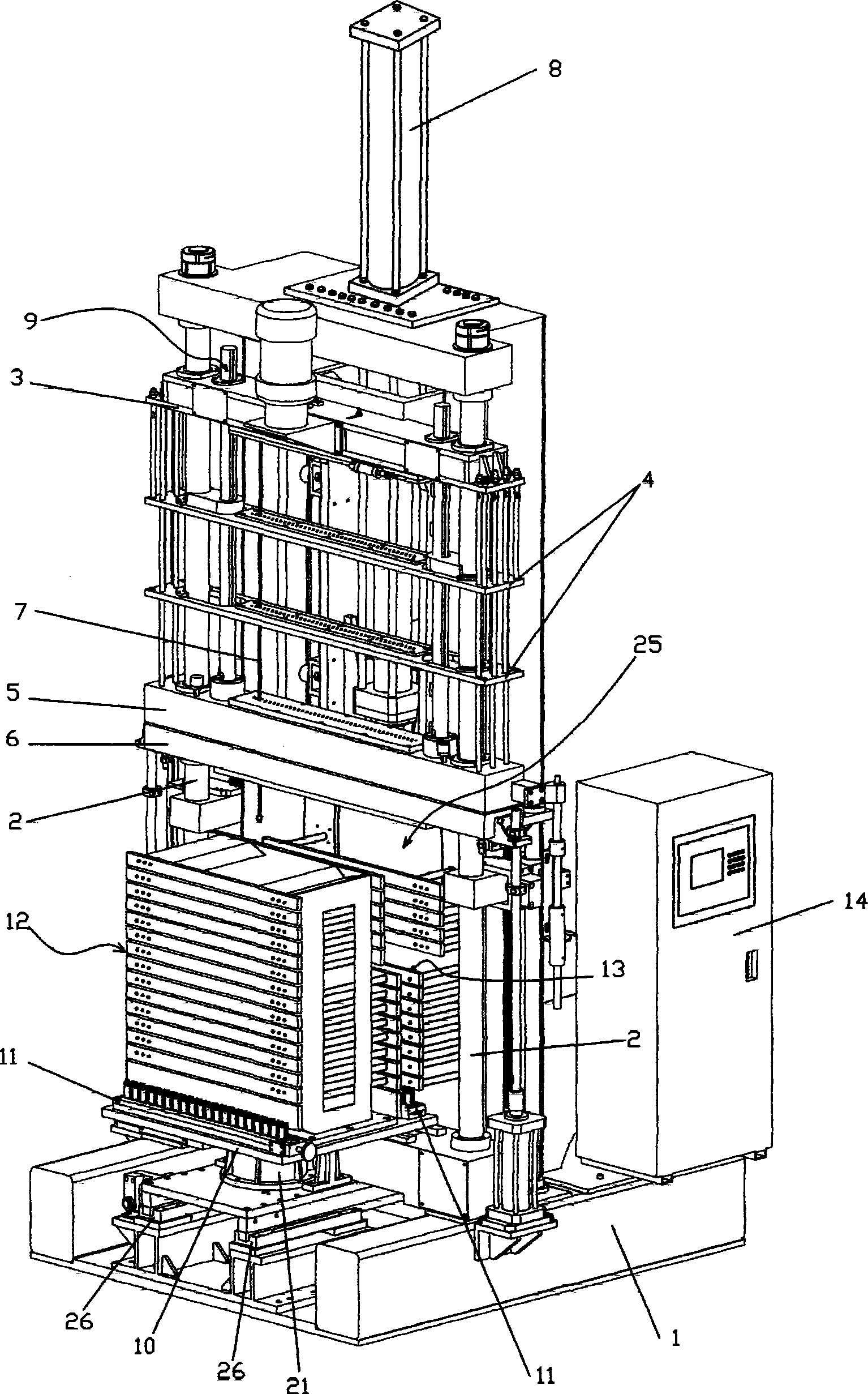
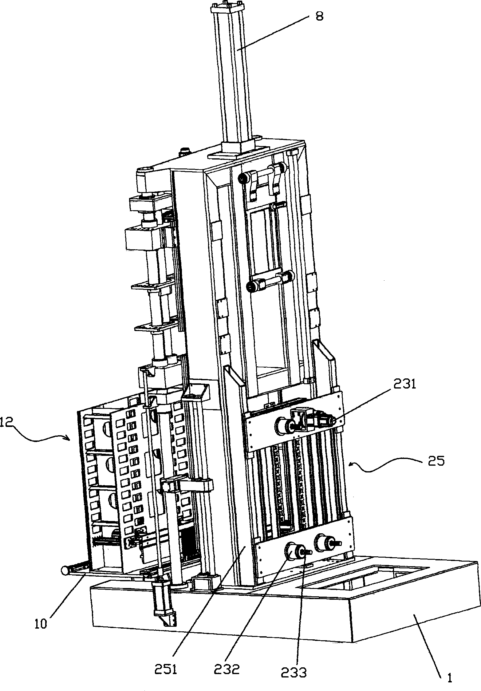
[0019] Such as figure 1 , figure 2 As shown, a vertical tube expander capable of automatic positioning and clamping includes a frame 1 on which two parallel guide posts 2 are vertically arranged, and a main oil cylinder 8 is provided on one side of the guide posts 2, The guide column 2 is sheathed with an expansion rod mold base 3 connected to the piston rod of the main oil cylinder 8, and the expansion rod mold base 3 is provided with an expansion rod 7; it also includes a stroke control mechanism 9 that can control the expansion rod mold base 3, The execution command of the stroke control mechanism 9 is issued by a controller 14; the expansion rod guide plate 4, the expansion die base 5, and the stripping plate 6 are connected in sequence under the expansion rod mold base 3; The rotary table 10 is provided with a workpiece positioning plate 11 and ...


PUM


Abstract

The invention discloses a vertical tube expander which can be automatically positioned and clamped and comprises a stander, two parallel guide pillars are vertically arranged on the stander, a master oil cylinder is arranged at one side of the guide pillars, an expanding rod die holder which is connected with a piston rod of the master oil cylinder is sleeved on each guide pillar through a penetrating way, and an expanding rod is arranged on the expanding rod die holder; the vertical tube expander comprises a stroke control mechanism which can control the expanding rod die holders, an execution instrument of the stroke control mechanism is sent by a controller; and an expanding rod guide plate, a flaring die holder and a material-returned plate are sequentially connected below the expanding rod die holders. The vertical rod expander is characterized by also comprising a rotary working table which is arranged at one side of the guide pillars, and a front clamping device is arranged on the rotary working table; an adjusting backplate device which is opposite to the rotary working table is arranged at the other side of the guide pillars, and a rear clamping device which is matched with the front clamping device is arranged on the adjustable backplate device. The invention has the advantages that the automaton degree is high, the labor intensity of an operator is reduced, and the productivity is greatly improved.

Description

【Technical field】 [0001] The invention relates to a vertical tube expander capable of automatic positioning and clamping. 【Background technique】 [0002] There is an important part in the air conditioner—the heat exchanger. In the production process of the heat exchanger, there is a process of processing many copper tubes placed in the heat sink. The cooling fins are in close contact to avoid loosening, and at the same time increase the thermal conductivity of the heat exchanger. On the other hand, the reserved ends of the copper tubes are expanded into a cup shape with a tapered edge to facilitate the next process. Connect to other copper pipes. The machine used in this process is a tube expander. According to the principle, it can be divided into hydraulic type and mechanical type. The principle of mechanical type is to use an expansion tube, and set an expansion ball larger than the diameter of the copper tube at the end. Under the action of external force, the expansio...

Claims


Application Information

Patent Timeline
IPC IPC(8): B21D39/20B21D41/02
Inventor 龙晓斌
Owner OMS MASCH CO LTD
Why Eureka
Try Eureka