Rapid shaping method for manufacturing metal laminated solid mass

A solid manufacturing, metal lamination technology, applied in the direction of manufacturing tools, metal processing equipment, welding equipment, etc., can solve the problems of poor mechanical properties, waste of cutting time, scraps cannot be removed, etc., to save forming time and improve mechanical properties. Effect

Inactive Publication Date: 2009-07-15
SHENZHEN UNIV
View PDF0 Cites 12 Cited by
  • Summary
  • Abstract
  • Description
  • Claims
  • Application Information

AI Technical Summary

Problems solved by technology

[0011] 1. In order to remove waste after forming, it is necessary to cut the hole-shaped part of each layer into a grid, which wastes cutting time
[0012] 2. For parts with fully enclosed holes in space, waste cannot be removed
[0013] 3. The metal sheets of each layer are welded by hot bonding or brazing mechanism, and the mechanical properties are poor

Method used


Image

  • Rapid shaping method for manufacturing metal laminated solid mass

Examples


Embodiment

[0035] Embodiment: A rapid prototyping method for manufacturing a metal laminated entity.

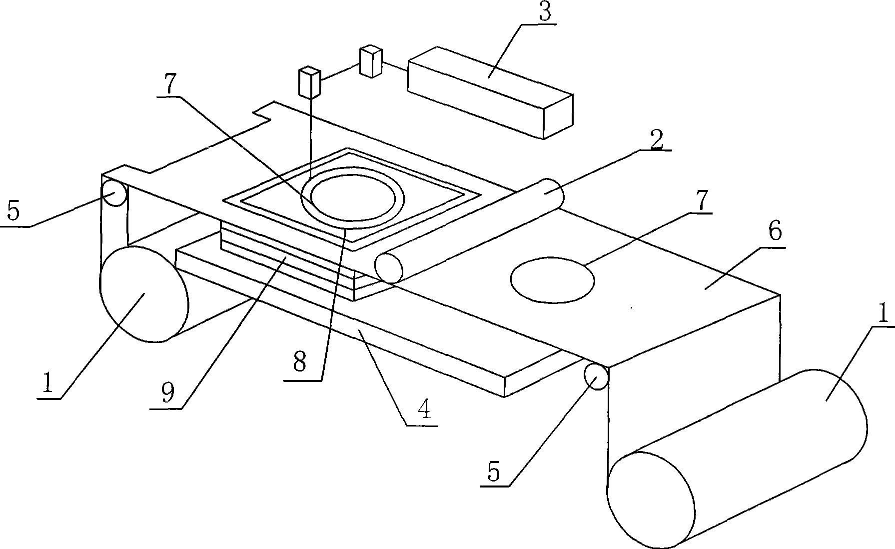
[0036] The device used in the rapid prototyping method of metal laminated entity manufacturing adopted in this embodiment is as follows figure 1 As shown, it consists of a computer (not shown in the figure), a raw material storage and feeding mechanism 1, a seam welding mechanism 2, a laser cutting system 3, a liftable workbench 4, guide rollers 5, a numerical control system and a frame (not shown in the figure) )composition. The sheet metal is 45# steel plate 6 with a thickness of 0.5 mm.

[0037] The specific forming process includes the following steps:

[0038] 1. Establish a CAD geometric model for metal parts and perform layered discretization;

[0039] 2. The raw material storage and feeding mechanism sends the 45# steel plate 6 stored therein to the first station above the liftable workbench 4;

[0040] 3. According to the contour line of the inner hole on the cross-section ...


PUM

PropertyMeasurementUnit
sizeaaaaaaaaaa

Abstract

A fast forming method for the manufacture of a metal laminated entity comprises the following steps of establishing a CAD geometrical model for metal parts, finishing the inner hole cutting of a metal sheet layer in a first work station through a laser cutting system, rejecting the wastes in the inner hole, welding the metal sheet with a metal sheet thereunder in a second work station through a welder, finishing the cutting of peripheral outline of the metal sheet layer in the second work station through the laser cutting system, and repeating the process between the steps 2 and 6 by moving a lifting working platform downwards (negative direction of Z) with a pace, until the metal sheets in the work piece are completely bonded or welded so as to obtain a formed work piece of metal laminated entity. Compared with the prior art, the invention thoroughly solves the forming problem of the parts with spatially totally-enclosed holes so as to greatly save time, can weld the metal sheet in each layer by smoothly using an electrical welding method, and remarkably improves the mechanical performance of the parts.

Description

technical field [0001] The invention relates to a method for manufacturing and forming metal parts, in particular to a rapid prototyping method for manufacturing a metal laminated entity. Background technique [0002] At present, a rapid prototyping machine (Laminated Object Manufacturing, LOM for short) is used for manufacturing a metal laminated entity. It is composed of computer, raw material storage and feeding mechanism, thermal bonding or brazing mechanism, laser cutting system, liftable worktable, guide roller, numerical control system and frame, etc. The functions of the above institutions are: [0003] 1) The computer is used to receive and store the three-dimensional model of the workpiece, extract a series of cross-sectional contour lines along the height direction of the model, and issue control instructions. [0004] 2) The raw material storage and feeding mechanism will gradually send the metal sheet with the bottom surface coated with hot melt adhesive store...

Claims


Application Information

Patent Timeline
Patent Type & Authority Applications(China)
IPC IPC(8): B23K11/00
Inventor 伍晓宇阮双琛程蓉梁雄郭小勤彭太江
Owner SHENZHEN UNIV
Why Eureka
Try Eureka