
Rotating cage type belt pulley of continuously variable transmission

A technology of working radius and pulley, which is applied in the direction of belt/chain/gear, elements with teeth, portable lifting devices, etc., to achieve the effect of reducing axial size, reducing strength and improving the range of change

Inactive Publication Date: 2013-12-18
宋佑群
View PDF4 Cites 0 Cited by
  • Summary
  • Abstract
  • Description
  • Claims
  • Application Information

AI Technical Summary

Problems solved by technology

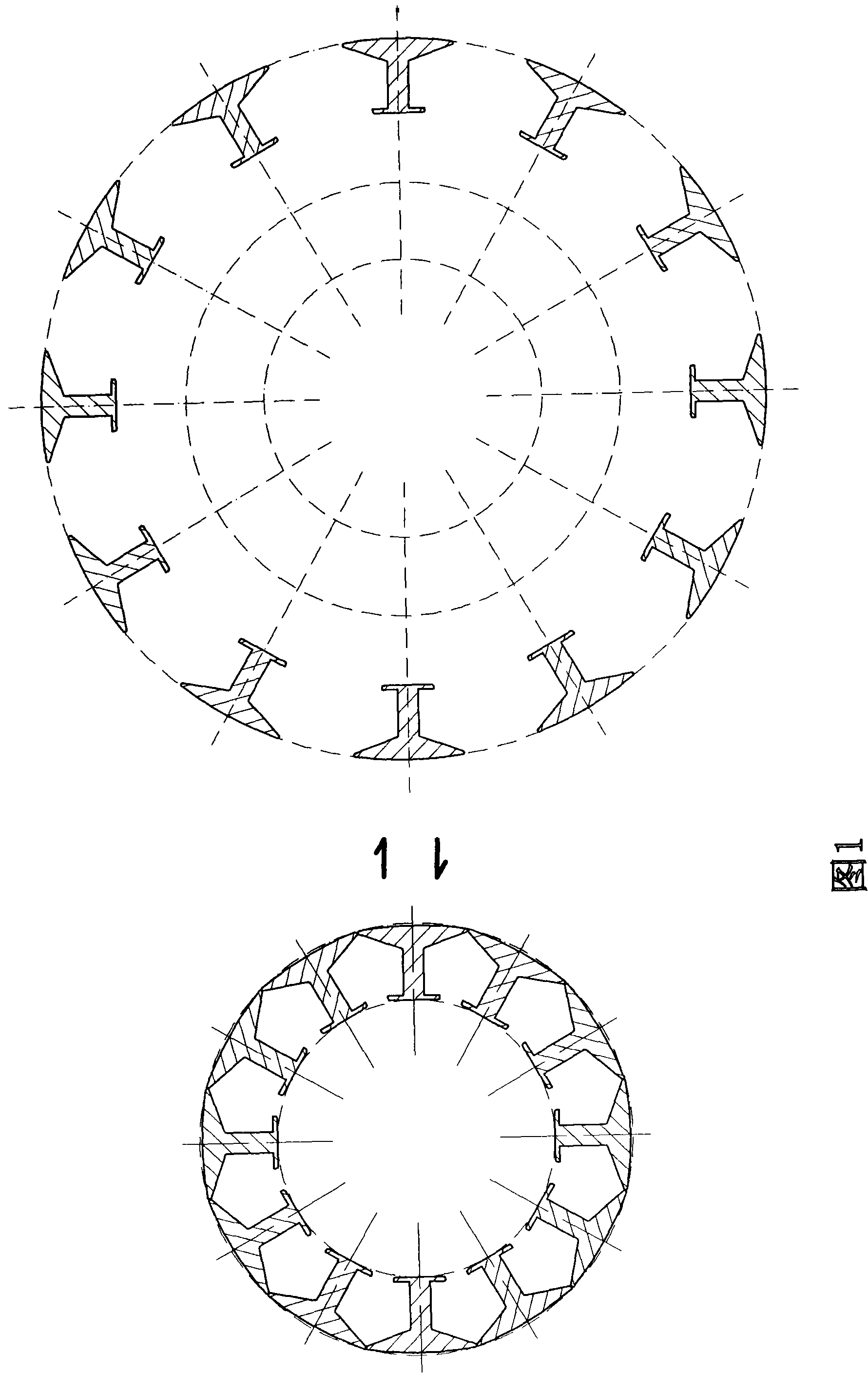
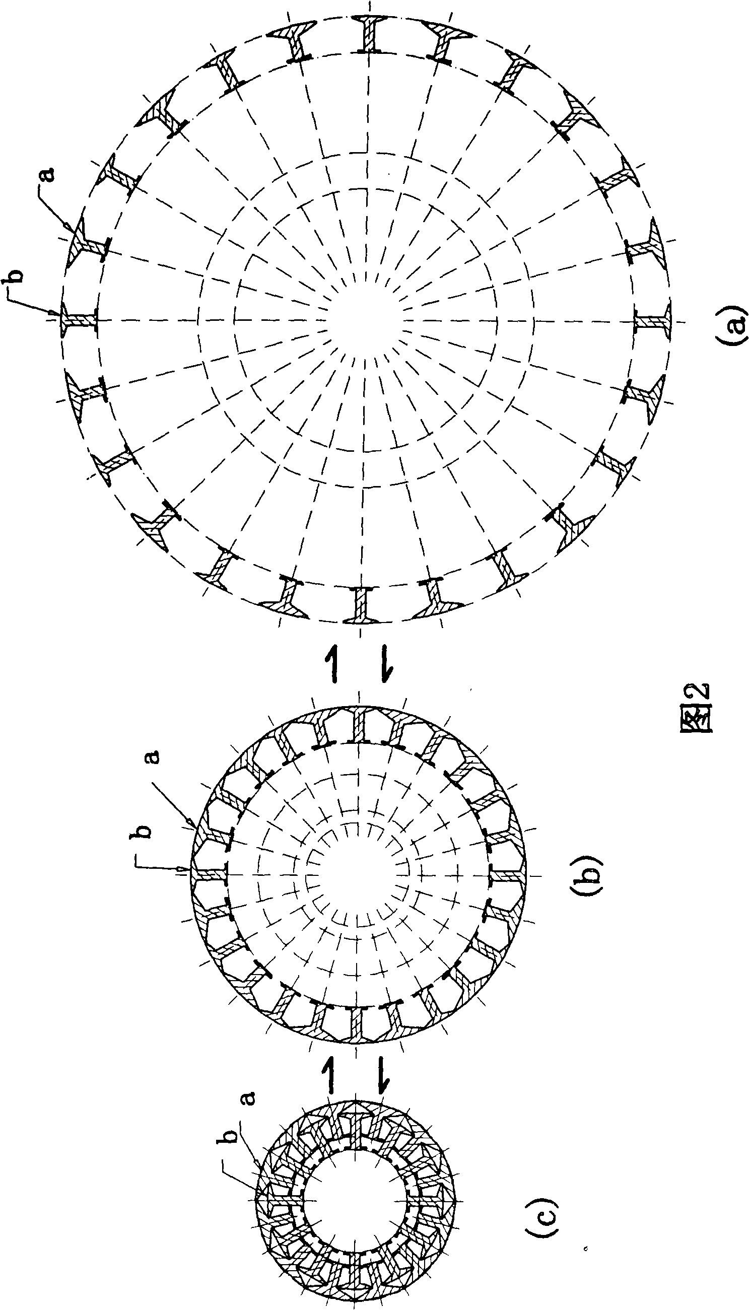
[0003] The purpose of this invention is to provide a rotating cage pulley that can continuously change the working radius, and solve the problem of replacing the existing axial movement with the radial movement of the working surface of the pulley. Movement to change the size of the working diameter of the driving and driven wheels can not only eliminate the damage caused by the lateral force of the belt during the diameter change, but also reduce the technical problem of the axial structural size; secondly, solve the technical problem of expanding the range of transmission ratio change

Method used


Image

  • Rotating cage type belt pulley of continuously variable transmission
  • Rotating cage type belt pulley of continuously variable transmission
  • Rotating cage type belt pulley of continuously variable transmission

Examples


Embodiment 1

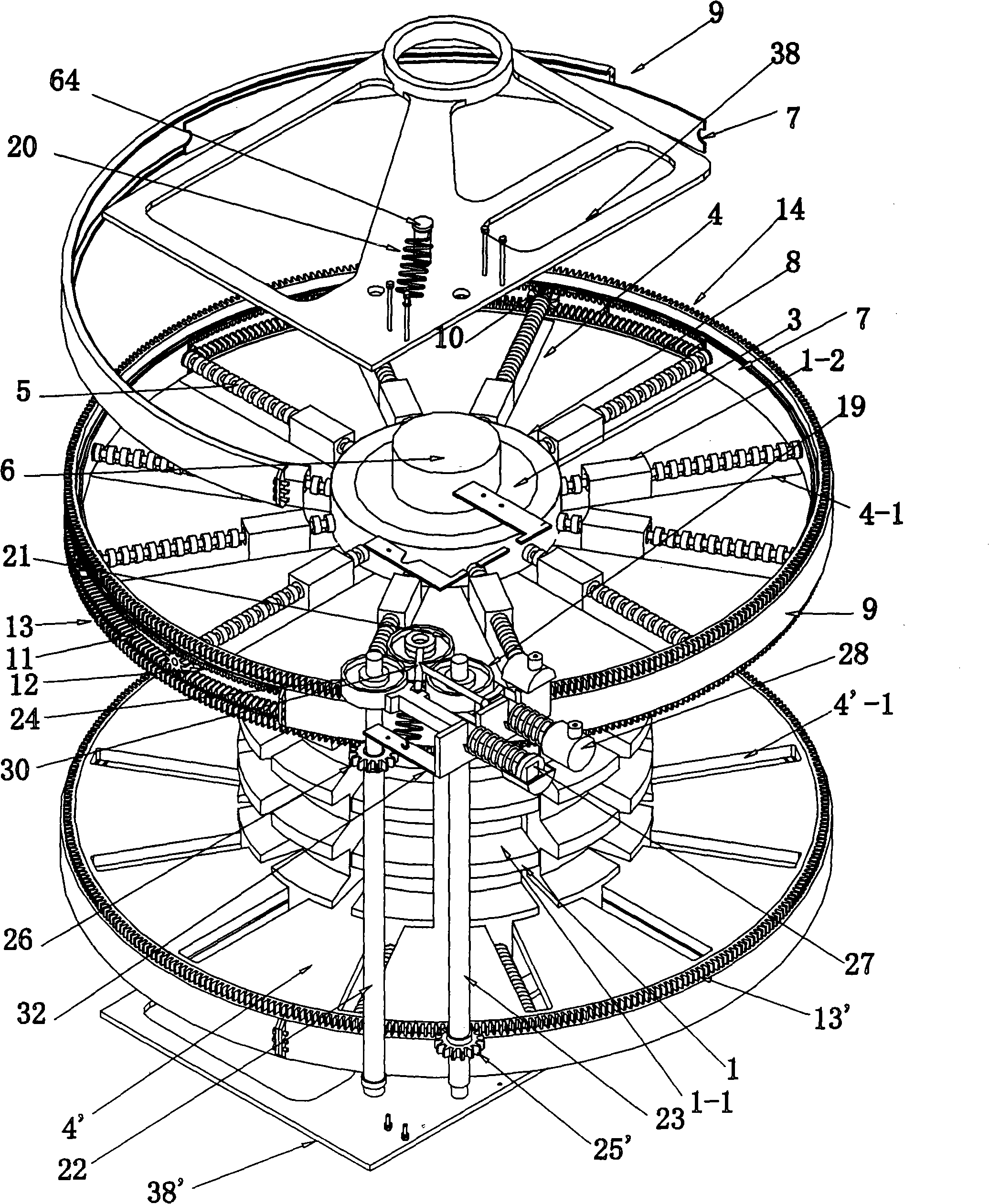
[0042] see Figure 5 , in a CVT composed of a pair of tumbler pulleys connected by the belt 2, when the working radius of the active tumbler pulley gradually decreases, the belt 2 starts to loosen, and the belt tensioner 35 is under the pressure of the tension spring 33 Under the action, move inwardly, pressure has sent out slack positioning sensor 40, and slack positioning sensor 40 sends signal to the second hydraulic cylinder 28 ' of another rotating cage pulley as driven wheel and carries out the same operation as above-mentioned driving wheel. The railing moves radially, but in the opposite direction, and the working radius gradually increases. When the belt 2 returns to the tensioned state, the slack positioning sensor 40 returns to its original state, and the second hydraulic cylinder 28' of the passive rotating cage pulley stops working, so that the active The reduction of the working diameter of the rotating cage pulley and the large variation of the working diameter ...

Embodiment 2

[0047] This embodiment is still the deformation of embodiment two, and the slide block 1-2 with the screw hole of its railing 1 is positioned at the middle part of railing 1 (referring to Figure 6 ), the band groove 1-1 on the railing 1 peripheral surface is located at the both sides of the railing 1, therefore, the torque disc 4, the spoke wheel, and the radius positioning control device are also centrally arranged, and its working process is the same as that of the second embodiment.

Embodiment 3

[0049] see Figure 7 As shown, the difference between the rotating cage pulley of this embodiment and the first to third embodiments is that the railing 1 and the screw 5 are divided into two groups of railing 1a and railing 1b, screw 5a and screw 5b at corresponding intervals, and the arc shape of the railing 1b The perimeter of the peripheral surface is less than the perimeter of the railing 1a, the screw rod 5b is engaged with an indicator 57, and the distance between the planetary positioning gear 10 on the screw rod 5b and the center of the wheel shaft is greater than the distance between the planetary positioning gear 10 on the screw rod 5a and the wheel shaft. The planetary positioning gear 10 arranged on the screw rod 5 a is only in mesh with the outer bevel gear 12 , the outer bevel gear 12 has no extended outer gear ring, and is provided with a retaining ring 15 and a screw lock. This retaining ring 15 is fixed with the torque disc 4 by means of screws, bolts or rive...


PUM


Abstract

The invention belongs to a power transmission part, in particular to a rotating cage typed belt roller of a variable speed case which comprises a wheel shaft and a wheel hub and is provided with a baluster, a large spoke frame, a small spoke frame and screws; wherein the surrounding surface of the top part of the baluster is one part of the circumference working surface of the belt roller; the side end thereof is provided with an extruding sliding block with a screw hole; the small spoke frame is fixed on the wheel hub; each screw is respectively meshed with the corresponding sliding block of the baluster; the shaft neck of the centripetal end of the screw is supported in the corresponding seat hole of the small spoke frame; the shaft neck of the centrifugal end of the screw spans the large spoke frame. The invention solves the technical problem of realizing the changes of the working radius of the belt roller by using the radial motion of the working surrounding surface of the belt roller to replace the axial motion.

Description

Technical field: [0001] The invention relates to power transmission components, in particular to a tumbler pulley which can continuously change the working radius and realize stepless speed change. Background technique: [0002] The existing continuously variable transmission device is through a pair of opposite conical runners that can move towards each other. The conical surfaces of the runners are relatively V-shaped grooves. The radius of the V-belt pulley becomes larger or smaller, so as to realize the continuous change of the transmission ratio of the active and passive V-belt pulleys. The device is axially controlled, so it takes up a large space, and the range of movement cannot exceed the width of the belt, and the width of the belt is limited by the thickness of the belt, so the change in transmission ratio is small. And because the belt in the V-belt pulley is forced to the outside of the wheel, this not only requires a strong axial pushing force, but also the c...

Claims


Application Information

Patent Timeline
Patent Type & Authority Patents(China)
IPC IPC(8): F16H55/54F16H61/662F16H7/08
Inventor 宋佑群
Owner 宋佑群
Learn More