

Thermoforming, hole-punching and edge-cutting integrated technique and mold of high-duty steel part
A high-strength steel, hot forming technology, applied in the direction of forming tools, piercing tools, manufacturing tools, etc., can solve the problem that high-strength steel parts cannot be formed and punched, forming, trimming or punching can not be combined, and cannot be used Problems such as punching or edge trimming of high-strength sheet metal achieve the effects of shortening the production cycle, high dimensional accuracy and shape accuracy, and reducing floor space
- Summary
- Abstract
- Description
- Claims
- Application Information
AI Technical Summary
Problems solved by technology
Method used
Image

Examples
Embodiment Construction
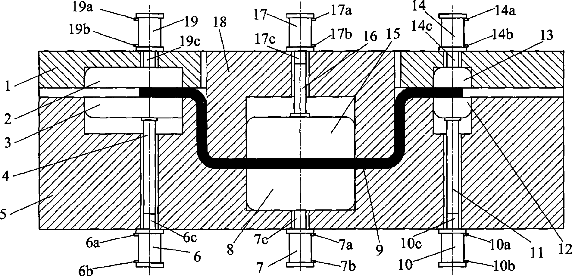
[0026] The hot forming, punching and trimming integrated process of the high-strength steel parts of the present invention, firstly, corresponding trimming and punching are arranged on the punch, die or binder plate of the hot-forming mold of the high-strength steel parts. Hole tools for mounting trimming and punching devices on punches, dies or binders. The flow of the process is that the sheet heated to the austenitic state is placed on the die of the thermoforming mold → driven by the press, the pressing plate first presses the thermoforming sheet, and then the punch and die are closed , to complete the thermoforming of the part → trimming and punching device movement in the punch, die or binder plate, complete trimming and punching → pass cooling medium into the punch, die or binder plate to cool the mold Cooling to achieve quenching of high-strength parts, while the trimming and punching tools are reset, and the waste formed by trimming and punching is ejected → Driven by...
PUM
 Abstract
Description
Claims
Application Information