Eureka AIR delivers breakthrough ideas for toughest innovation challenges, trusted by R&D personnel around the world.

Flat cut type plate-casting machine

A plate casting machine and flat cutting technology, which is applied in the field of lead alloy grid, can solve the problems of deformation of lead alloy grid size, difficulty in replacing valve core, quantitative lead supply of lead leakage, etc., so as to achieve reasonable structure and reduce production The effect of strength and operating cost, and easy replacement

Active Publication Date: 2009-07-22
武汉深蓝自动化设备股份有限公司
View PDF0 Cites 15 Cited by
  • Summary
  • Abstract
  • Description
  • Claims
  • Application Information

AI Technical Summary

Problems solved by technology

[0003] At present, there are two kinds of known lead valves: a kind of lead valve is a cone-tip cone-face sealing valve exposed to the air. Lack of sealing leads to lead leakage and inaccurate quantitative lead supply; another kind of lead valve is a ceramic ball cone sealing valve embedded in the lead liquid. The valve core of this lead valve is installed in the pump body and locked with the valve core gland. When replacing the spool, the lead pipe and the whole lead pump must be unloaded first, and it is difficult to replace the spool
[0004] At present, the known cutting dies all use an angle of about 40-50° to cut off the process gate of the lead alloy grid. Before cutting, the positioning method of the lead alloy grid with the process gate is to locate on the inclined plane in the direction of the angle of 40-50° , the way for the lead alloy grid with process gate to enter the cutter mold is to rely on the weight of the lead alloy grid to overcome the friction force of the slope of the lower knife seat with an angle of 40-50°, then accelerate to slide down freely and hit the lower positioning When positioning the plate, the lead alloy grid freely accelerates and slides down obliquely and hits the lower positioning plate, which will cause a large deformation of the lead alloy grid.

Method used


Image

  • Flat cut type plate-casting machine
  • Flat cut type plate-casting machine
  • Flat cut type plate-casting machine

Examples


Embodiment Construction

[0036] The present invention will be described in further detail below in conjunction with the accompanying drawings.

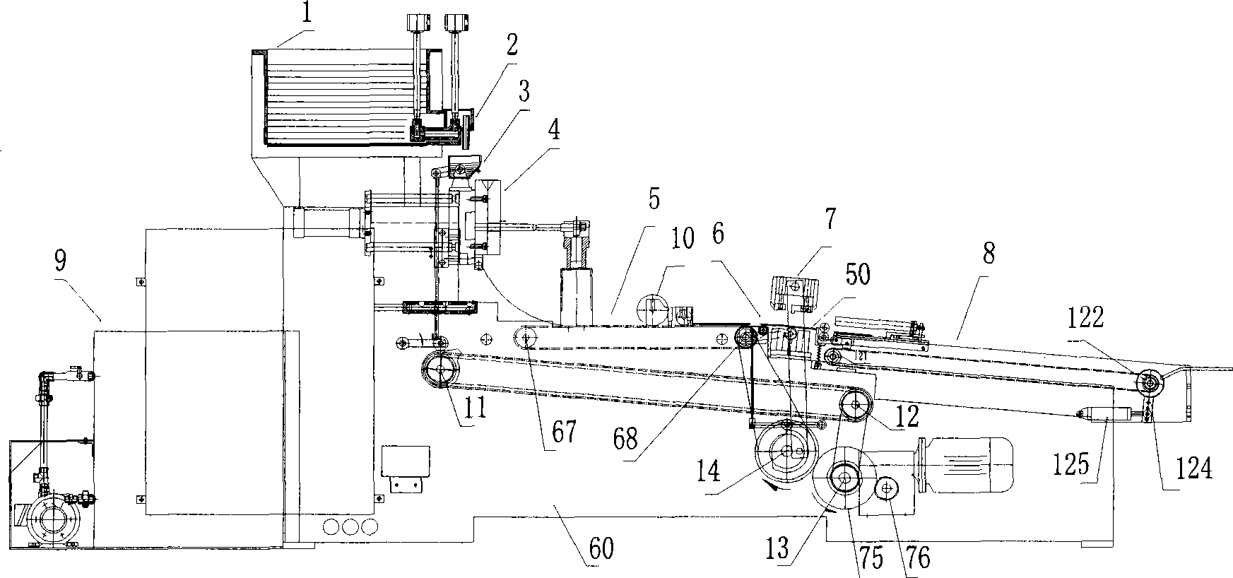
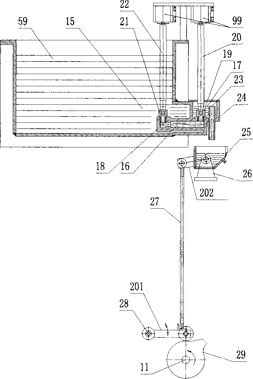
[0037] Figure 1A It is a schematic diagram of the overall structure of the flat-cut casting machine according to the present invention, including a high-level lead melting furnace 1 provided with a series lead valve device 2, and a lead spoon pouring mechanism 3 is arranged sequentially below the series lead valve device 2 And the mold opening and closing mechanism 4, the left side of the mold opening and closing mechanism 4 is provided with a circulating water tank 9, and the right side is successively provided with a shaping conveying mechanism 5, a grid horizontal positioning mechanism 6, a flat cutting knife mold 7 and a grid Film receiving mechanism 8; Wherein, three parts of serial lead valve device, plate grid horizontal positioning mechanism and flat cut-off type cutter mold are the key parts that the present invention overcomes the defect of prior ar...


PUM


Abstract

The invention relates to a truncated slab casting machine, in particular to a lead alloy slab lattice casting and forming device for manufacturing a lead-acid accumulator. The lead alloy slab lattice casting and forming device comprises a production line device which is formed by connecting a high-level lead smelting furnace, a tandem lead valve gear, a lead scoop lead turnover mechanism, a die switching die mechanism, a reshaping and conveying mechanism, a slab lattice horizontal positioning mechanism, a truncated cutting-knife die, a slab lattice receiving mechanism and a circulating water tank in sequence. The device is cooperatively operated under automatic electric control. The truncated slab casting machine adopts the tandem lead valve gear, the slab lattice horizontal positioning mechanism and the truncated cutting-knife die, is accurate to quantitatively supply lead and convenient to replace valve cores, makes lead alloy slab lattices horizontally positioned on a lower positioning plate at a uniform velocity to realize non-deformation of the lead alloy slab lattices, realizes automatic casting forming of the lead alloy slab lattices, completes transformation of the production flow from manual labor to automatic operation, greatly reduces the production strength and the operation cost of manual operation, guarantees the casting quality of quantitative and accurate supply of the leads, convenient replacement of the valve cores and non-deformation of the lead alloy slab lattices, and improves the labor productivity.

Description

technical field [0001] The invention relates to lead alloy grid casting equipment in the manufacture of lead-acid batteries, in particular to a flat-cut casting machine for producing lead alloy grids of lead-acid batteries. Background technique [0002] In the production process of lead-acid batteries, it is necessary to produce lead alloy grids with qualified dimensions, and the lead alloy grids are mainly produced by casting machines. The casting machine includes a high-level lead melting furnace (or a low-level lead melting furnace), a lead valve device, a lead spoon pouring mechanism, a mold opening and closing mechanism, a shaping and conveying mechanism, a grid slope positioning mechanism, an inclined cutter mold, and a grid Take-up mechanism and circulating water tank. [0003] At present, there are two kinds of known lead valves: a kind of lead valve is a cone-tip cone-face sealing valve exposed to the air. Lack of sealing leads to lead leakage and inaccurate quant...

Claims


Application Information

Patent Timeline
IPC IPC(8): B22D25/04
Inventor 周世伟
Owner 武汉深蓝自动化设备股份有限公司
Why Eureka
Eureka Blog
Learn More