Micro-channel heat sink for semi-conductor laser

A micro-channel and laser technology, applied in the direction of semiconductor lasers, lasers, laser parts, etc., can solve the problems of difficult production, poor mechanical strength and high cost, reduce the difficulty of connection and processing cost, improve heat dissipation capacity, and increase mechanical strength. the effect of strength

Inactive Publication Date: 2009-07-22
SHANXI FEIHONG MICRO NANO PHOTOELECTRONICS SCI & TECH
View PDF0 Cites 6 Cited by
  • Summary
  • Abstract
  • Description
  • Claims
  • Application Information

AI Technical Summary

Problems solved by technology

[0003] In order to solve the problems in the background technology, due to the combination of the microchannel side walls (radiation ribs) and the microchannel top wall (heat transfer layer) through welding technology to introduce additional thermal resistance, the entire microchannel heat sink has many welding interfaces and the microchannel components are uniform. It is the problem of poor performance, poor mechanical strength, high manufacturing difficulty and high cost caused by the flat plate structure. The present invention provides a new type of semiconductor laser microchannel heat sink, which not only reduces the microchannel heat sink of high power semiconductor laser Production difficulty and production cost, while also improving the overall performance and mechanical strength of the device

Method used


Image

  • Micro-channel heat sink for semi-conductor laser
  • Micro-channel heat sink for semi-conductor laser
  • Micro-channel heat sink for semi-conductor laser

Examples


Embodiment Construction

[0022] Describe the present invention in detail below in conjunction with accompanying drawing and specific embodiment, but the present invention is not limited to these embodiments:

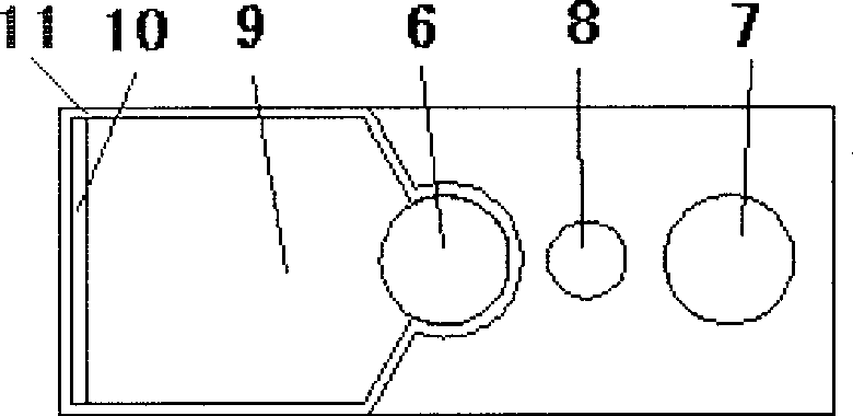
[0023] The structure of this embodiment is as Figure 8 , Figure 9 and Figure 10 As shown, it includes a cover plate 1, a water distribution seat 2 and a bottom plate 3, the cover plate 1 is located above the water distribution seat 2, and the two are fixedly connected. The bottom plate 3 is located under the water distribution seat 2, and the two are also fixedly connected.

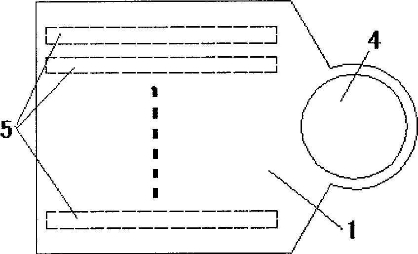
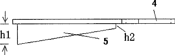
[0024] The structure of cover plate 1 is as follows figure 1 , figure 2 As shown, the cover plate 1 is provided with the first water inlet 4 to the right, and the lower surface of the cover plate 1 is provided with the microchannel wall 5 to the left, and between the adjacent two microchannel walls 5 is a space for cooling water to flow through. The microchannel, and the height h1 of the microchannel wall 5 on the ...


PUM


Abstract

The invention relates to a semiconductor laser microchannel heat sink which belongs to the semiconductor optoelectronic technical filed. To improve unfavorable situations of poor structural performance, great process difficulty, high cost and the like of the high power semiconductor laser microchannel heat sink, the invention replaces the prior five-layer structure by three-layer, and then reduces difficulty and cost of fabrication, improves mechanical strength and improves the whole heat dispersion by utilizing altitude variation of microchannel wall. The new microchannel heat sink structure applies to the present preparation of any semiconductor laser embattle and stack arrays.

Description

technical field [0001] The invention relates to a microchannel heat sink structure for a semiconductor laser, belonging to the technical field of semiconductor optoelectronics. Background technique [0002] At present, microchannel heat sinks for high-power semiconductor lasers generally use five layers of high thermal conductivity rectangular sheet materials with different internal hollow structures to form a microchannel heat sink structure. This structure requires precise processing of five layers of highly thermally conductive rectangular sheet materials, and then uses welding technology to accurately and tightly bond them together. This structure introduces additional thermal resistance due to the combination of the microchannel side wall (radiating fin) and the microchannel top wall (heat transfer layer) through welding technology, which greatly increases the overall thermal resistance of the structure; The four interfaces involve the welding process, which makes weld...

Claims


Application Information

Patent Timeline
Patent Type & Authority Applications(China)
IPC IPC(8): H01S5/024
Inventor 尧舜王智勇刘江
Owner SHANXI FEIHONG MICRO NANO PHOTOELECTRONICS SCI & TECH
Why Eureka
Try Eureka