Supercharge Your Innovation With Domain-Expert AI Agents!

Valve device

A valve device and valve rod technology, which is applied in the direction of valve device, valve lift, valve details, etc., can solve the problem of brittle failure of the welding part of the valve rod, and achieve the effect of improving reliability and preventing peeling

Active Publication Date: 2009-07-22
MITSUBISHI POWER LTD
View PDF3 Cites 2 Cited by
  • Summary
  • Abstract
  • Description
  • Claims
  • Application Information

AI Technical Summary

Problems solved by technology

[0014] In addition, it has also been confirmed that when a short circuit or emergency load interruption occurs when the valve rod is welded, the valve rod may receive a large impact, which may easily cause brittle fracture of the welded part of the valve rod.

Method used


Image

  • Valve device
  • Valve device
  • Valve device

Examples


Embodiment

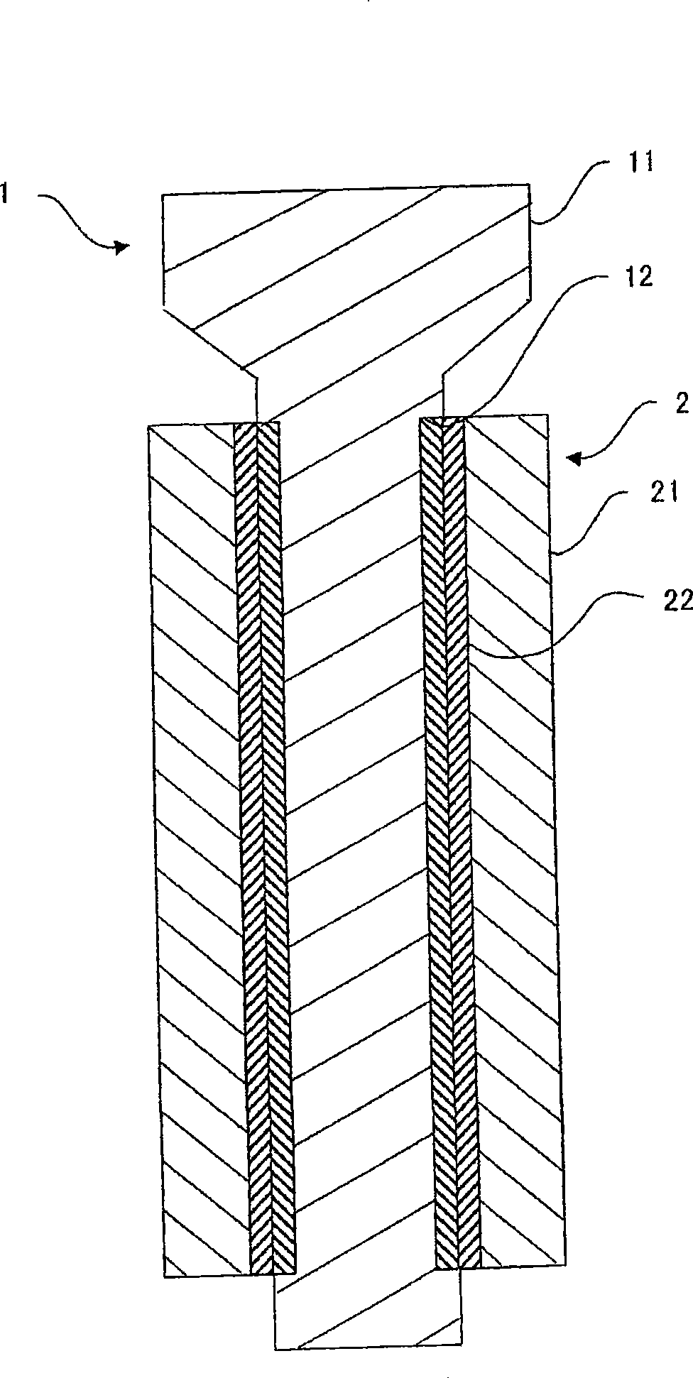
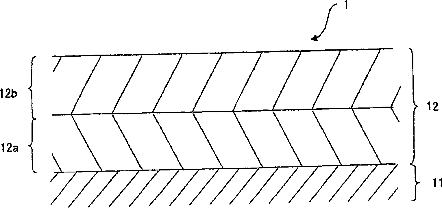
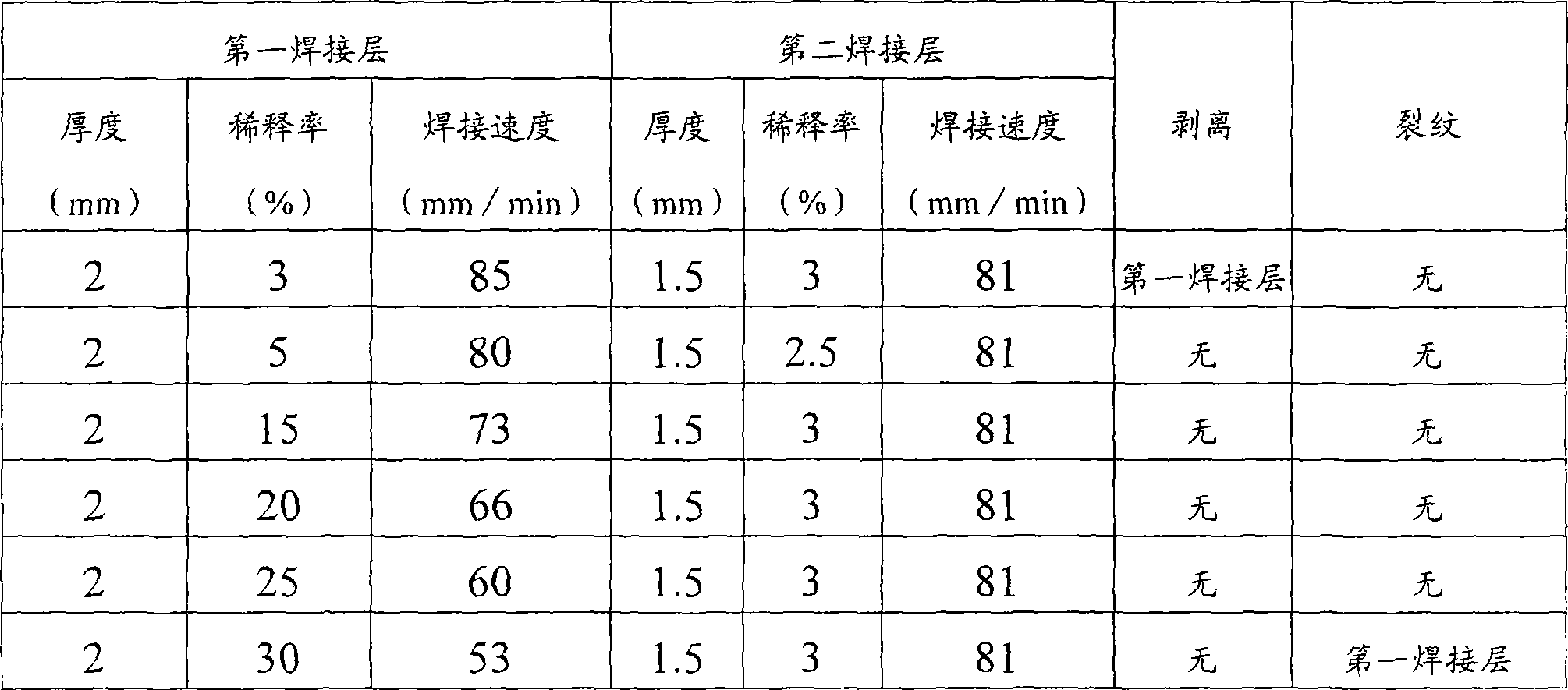
[0055] 1.2%Cr-0.3%Mo steel (JIS SCM3) was prepared. Plasma powder build-up welding was performed on the plate-shaped steel material (base material) in the following manner. Additionally, if figure 2 As shown, the plasma powder surfacing is set to two layers and the dilution rate is changed. Dilution rate is passed as figure 2 Adjust by changing the welding speed as shown. in addition, figure 2 In the above, the first welding layer is the welding layer formed on the surface of the base material, and the second welding layer is the welding layer formed on the surface of the first welding layer. After the first welding layer is formed, the surface is ground and ground to achieve figure 2 Thickness indicated. Thereafter, after forming the second solder layer, the surface is ground and ground to achieve figure 2 Thickness indicated.

[0056] Steel preheating temperature: 300°C

[0057] Welding speed: 60~80mm / min

[0058] Auxiliary gas: Ar gas (temperature: 20°C)

[...


PUM

PropertyMeasurementUnit
dilution factoraaaaaaaaaa

Abstract

It is intended to enhance the reliability of a valve gear obtained by plasma powder deposit welding of a cobalt base alloy. There is provided a valve gear equipped with a bearing having a slide face with valve rod (1), comprising weld layer (12) resulting from plasma powder deposit of a heat-resisting cobalt base alloy on the slide face with valve rod (1), which weld layer (12) includes first weld layer (12a) of 5 to 25% dilution ratio formed on the surface of the bearing and second weld layer (12b), formed on the first weld layer (12a), whose dilution ratio is 50% or less of that of the first weld layer (12a). The dilution ratio is a parameter indicating the amount of weld metal having infiltrated in the base material, and refers to a value calculated by the formula B / A OE100 (%) in which A is the total amount of metal used in welding and B the amount of weld metal having infiltrated in the base material.

Description

technical field [0001] The present invention relates to a valve device, in particular to a valve device capable of preventing a valve rod of a steam valve from being stuck between a bearing supporting the valve rod. Background technique [0002] The main steam valve of the steam turbine is used under severe conditions of high temperature and high pressure, and is responsible for controlling the high-speed steam flow. At high temperature, the metal surface is in an activated state, and reacts with the high-temperature water vapor in the gas environment to form an oxide film. The adhesion strength of the generated oxide film to the base material varies depending on the composition of the base material and the surrounding environmental conditions. When the valve repeatedly opens and closes, it will peel off, and due to the sliding of the valve rod, it will be locally deposited in the concave part of the surface. Buried in the gap between the valve rod and the bearing, sometime...

Claims


Application Information

Patent Timeline
Patent Type & Authority Applications(China)
IPC IPC(8): B23K10/02B23K9/04F16K1/32
CPCB23K10/027F16K27/00Y10S384/912Y10S384/913
Inventor 武井真男西村利也广畑贵彦蟹川昌也
Owner MITSUBISHI POWER LTD
Features
  • R&D
  • Intellectual Property
  • Life Sciences
  • Materials
  • Tech Scout
  • Unparalleled Data Quality
  • Higher Quality Content
  • 60% Fewer Hallucinations
Learn More