Inlet manifold assembly

An intake manifold and assembly technology, applied in the field of auto parts, can solve the problems of large installation and layout space, large fuel leakage, and difficulty in distinguishing the external hoses of the fuel rail, so as to improve utilization rate, reduce leakage, and arrange neat effect

Active Publication Date: 2009-07-29
ZHEJIANG GEELY HLDG GRP CO LTD
View PDF1 Cites 4 Cited by
  • Summary
  • Abstract
  • Description
  • Claims
  • Application Information

AI Technical Summary

Problems solved by technology

[0004] The present invention mainly provides an intake manifold assembly which is neatly arranged in the engine compartment, the fuel rails of the two fuels are clearly arranged, the external hoses of the fuel rails are easy to distinguish...

Method used


Image

  • Inlet manifold assembly
  • Inlet manifold assembly
  • Inlet manifold assembly

Examples


Embodiment

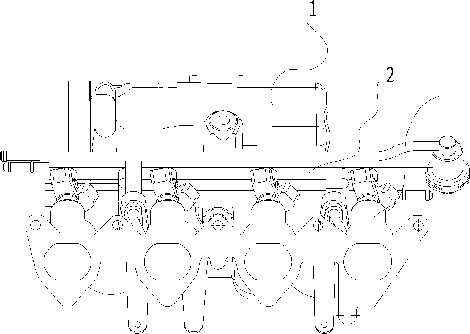
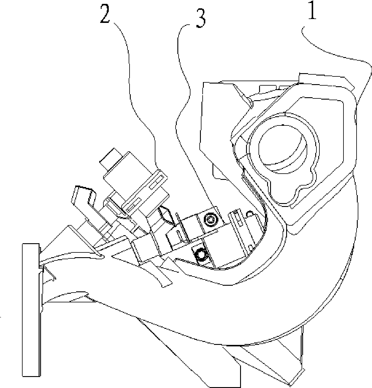
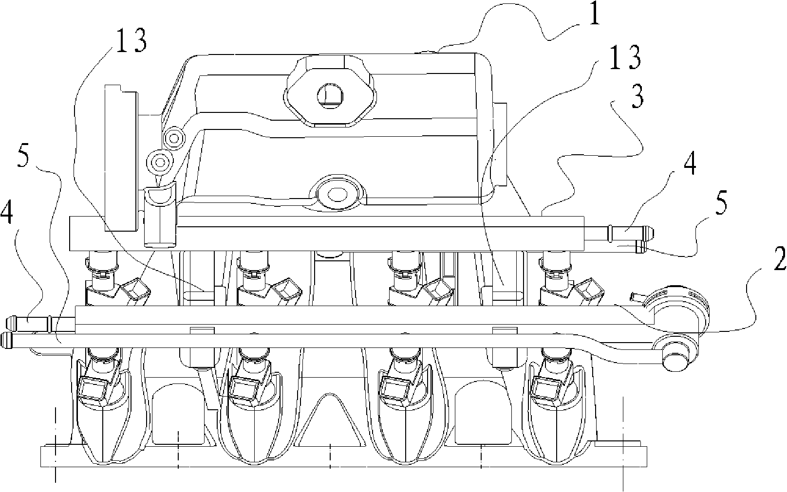
[0029] like figure 1 and 2As shown in and 3, an intake manifold assembly includes an intake manifold 1 and an oil rail assembly installed on the intake manifold 1. The intake manifold 1 is installed with two sets of oil rail assemblies arranged in front and rear. The ports of the oil inlet pipe 4 and the oil return pipe 5 on the same set of oil rail assemblies are located on the same side as the connecting ends of the external hoses. The connection ends of one set of oil rail assembly 2 and the connection ends of the second set of oil rail assembly 3 in the rear row are respectively located on both sides of the intake manifold 1 . The first set of fuel rail assembly 2 is a methanol fuel rail assembly, the second set of fuel rail assembly 3 is a gasoline fuel rail assembly, methanol is the main fuel, and gasoline is used as a start-up and backup fuel. The ports of the oil inlet pipe 4 and the oil return pipe 5 of the first oil rail assembly 2 are located on the left side of t...


PUM

PropertyMeasurementUnit
Angleaaaaaaaaaa

Abstract

The invention relates to a part used for an automobile engine, in particular to an intake manifold applied to a dual-fuel automobile engine. The invention comprises an intake manifold body which is equipped with an intake manifold connecting seat used for connection, a fuel nozzle mount pad and an oil track mount pad which are integral with the intake manifold body are arranged at the position close to the intake manifold connecting seat, the fuel nozzle mount pad comprises two groups of nozzle mount holes, and the oil track mount pad is arranged above the air intake channel and provided with two groups of oil track mount holes. The invention mainly aims at providing a dual-fuel intake manifold which uses two groups of fuel nozzles to provide dual fuel, and the phenomena affecting the fuel nozzle performance between the two groups of fuel nozzles such as oil film deposition and coverage at the mount holes of the fuel nozzles do not appear; and the invention resolves the technical problems existing in the prior art that only single point injection is employed and meanwhile the lower fuel nozzle can produce oil film deposition and coverage, thus affecting the performance of the lower fuel nozzle.

Description

technical field [0001] The invention relates to an automobile part, in particular to an intake manifold assembly applied to a dual-fuel automobile. Background technique [0002] With the development of industrial technology, automobiles have become an important means of transportation for people. At present, the main fuel for automobiles is gasoline, which is a non-renewable fuel and causes pollution to the environment. New type of fuel is expected by people, and now the sources of fuel for automobile engines are beginning to diversify, and more and more people pay attention to dual-fuel vehicles. Corresponding to the dual-fuel supply system, as an important part of the intake manifold assembly, which delivers fuel and air for combustion to the engine, its structure must be modified accordingly. The intake manifold assembly is generally composed of the intake manifold and the fuel rail assembly on it. The oil inlet on the intake manifold corresponds to the nozzle installat...

Claims


Application Information

Patent Timeline
IPC IPC(8): F02M35/104F02M61/14
CPCF02M61/145F02D19/0692F02D19/0678F02M35/112F02D19/0697Y02T10/36F02M43/04F02M37/0052F02D19/0655F02M35/10216F02M35/10111F02M37/0064Y02T10/30
Inventor 宋金环金先扬
Owner ZHEJIANG GEELY HLDG GRP CO LTD
Why Eureka
Try Eureka