
Propagation delay based transmit power control

A transmission power and power control technology, applied in the direction of transmission control/equalization, power management, electrical components, etc., can solve the problems of transmission power interference, complexity, and increase in target signal quality, so as to increase battery consumption, stabilize wireless networks, The effect of high average power

Inactive Publication Date: 2009-07-29
TELEFON AB LM ERICSSON (PUBL)
View PDF4 Cites 8 Cited by
  • Summary
  • Abstract
  • Description
  • Claims
  • Application Information

AI Technical Summary

Problems solved by technology

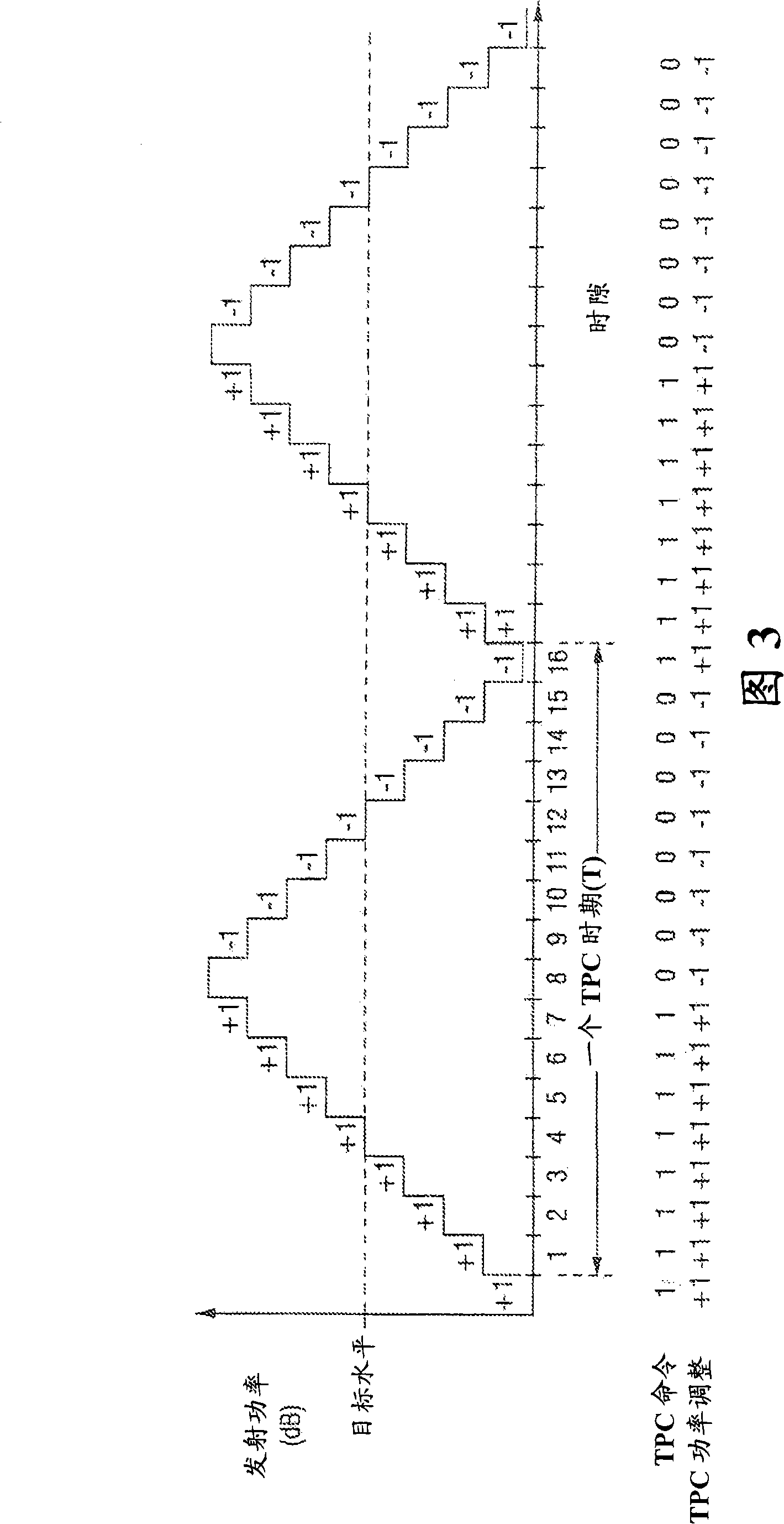
First, the transmit power level has a higher peak causing greater interference to other users of the system
Second, higher peak oscillations can lead to instability in wireless networks
Third, since the oscillation peaks have higher amplitudes, the target signal quality will have to be increased so that negative oscillation peaks do not drop below the minimum desired signal quality
While quite accurate and comprehensive, this approach can be more complex than necessary in some cases
Also, there may be existing base stations and / or mobile stations built using ASICs and / or other hardware that are unsuitable for implementing methods requiring significant additional data processing

Method used


Image

  • Propagation delay based transmit power control
  • Propagation delay based transmit power control
  • Propagation delay based transmit power control

Examples


Embodiment Construction

[0034] In the following description, for purposes of explanation and not limitation, specific details are set forth, such as specific nodes, functional entities, techniques, protocols, standards, etc., in order to provide an understanding of the described techniques. It will be apparent to those skilled in the art that other embodiments may be practiced without the specific details disclosed below. In other instances, detailed descriptions of well-known methods, devices, techniques, etc. are omitted so as not to obscure the description with unnecessary detail. Individual functional blocks are shown in the figure. Those skilled in the art will appreciate that the functions of those blocks may be implemented using individual hardware circuits, using software programs and data in conjunction with a suitably programmed microprocessor or general purpose computer, using an application specific integrated circuit (ASIC), and / or using a Or multiple digital signal processors (DSP) to ...


PUM


Abstract

The transmit power of a radio transmitter associated with a transmitting node communicating with a receiving node is controlled based on a propagation delay time associated with communication between the transmitting node and the receiving node. A power control loop is established for controlling a transmission power level for transmitting a signal from the transmitting node to the receiving node. A response time of the power control loop is reduced based on the propagation delay time.

Description

technical field [0001] The technical field is wireless communication, more specifically wireless transmission power control. One non-limiting application is for cellular communication systems. Background technique [0002] In a cellular communication system, mobile radio stations communicate with radio base stations via assigned radio channels. Sometimes a mobile station (MS) is grouped under the term user equipment (UE). These terms are used interchangeably herein with the understanding that a mobile station / UE includes both mobile and fixed wireless communication devices. Some base stations are coupled to switching nodes, which are typically connected to gateways that interface the cellular communication system with other communication systems. A call placed to a mobile station from an external network is directed to a gateway, and from the gateway through one or more switching nodes to a base station serving the called mobile station. The base station pages the called...

Claims


Application Information

Patent Timeline
Patent Type & Authority Applications(China)
IPC IPC(8): H04B7/005H04W52/08H04W52/36
CPCH04W52/54H04W52/362H04W52/08H04W52/22
Inventor J·彼得森T·奥斯特曼
Owner TELEFON AB LM ERICSSON (PUBL)
Learn More