Sputtering film-plating apparatus

A technology of sputtering coating and air inlet, which is applied in sputtering coating, ion implantation coating, vacuum evaporation coating, etc. It can solve the problem that the uniformity of film thickness cannot be effectively controlled, and achieve the effect of convenient operation

Active Publication Date: 2009-08-05
CSG HOLDING
View PDF0 Cites 11 Cited by
  • Summary
  • Abstract
  • Description
  • Claims
  • Application Information

AI Technical Summary

Problems solved by technology

[0005] The technical problem to be solved by the present invention is to provide a method that can control the uniformity of the film thickness in the sputtering coating process in view of the defect that the uniformity of the film thickness of the coating product cannot be effectively controlled in the sputtering coating process in the prior art. A device for realizing on-line adjusted sputtering coating

Method used


Image

  • Sputtering film-plating apparatus
  • Sputtering film-plating apparatus
  • Sputtering film-plating apparatus

Examples


Embodiment Construction

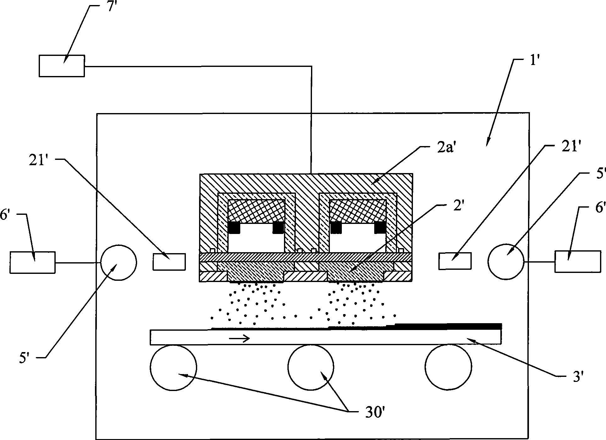
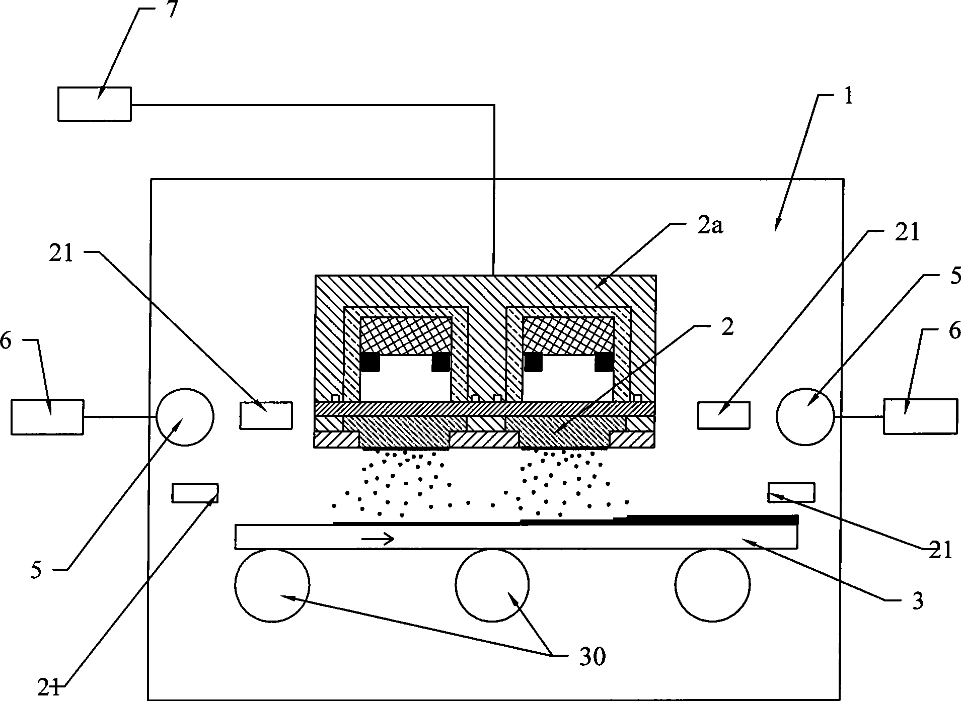
[0018] like figure 2 As shown, in a preferred embodiment of the sputter coating device of the present invention, a vacuum chamber 1 is included, and a cathode target 2, a substrate 3, an anode 5, and an air inlet 21, An air supply system 20 composed of an air supply channel 22 and an air source 23 . Wherein, the anode 5 is electrically connected to the anode power supply 6 outside the cavity 1, and the cathode target 2 is electrically connected to the cathode power supply 7 outside the cavity 1; The transmission mechanism 30 is driven to move forward, so that the whole process can be carried out continuously. The length direction of the cathode target 2 is set to be perpendicular to the traveling direction of the substrate 3, so that the cathode target 2 can scan the film surface of the entire substrate when the substrate 3 is advancing, and can cooperate with a cover plate with a pattern on the film surface of the substrate 3 Film layers of various patterns are sputtered. ...


PUM


Abstract

The invention relates to a sputtering coating device which comprises a vacuum chamber, an anode target, a cathode target, a coating product and a gas supply system, wherein the anode target and the cathode target are arranged in the vacuum chamber, the gas supply system comprises gas inlets and gas supply channels for communicating an external gas source and the gas inlets, wherein the gas inlets are arranged into a plurality of sections on the length direction along the cathode target, and a gas-flow controller used for independently controlling the sorts and the flow rates of process gases of each gas inlet is arranged on the gas supply channel communicated with each gas inlet. As the gas inlets in the gas supply system are arranged into a plurality of sections which are distributed on the length direction along the cathode target, and the gas-flow controller is arranged on the gas supply channel corresponding to each gas inlet, the sorts and the flow rates of gases in all gas supply channels can be controlled, thereby further locally and dynamically adjusting the process gases near the cathode target in the vacuum chamber. During the production process of a coating, the on-line adjustment of the evenness of the thickness of the coating can be achieved by adjusting the distribution states of the process gases by adjusting all gas-flow controllers in time.

Description

【Technical field】 [0001] The invention relates to a film coating device, more specifically, to a sputtering film coating device. 【Background technique】 [0002] Under vacuum conditions, positively charged particles are used to bombard the negatively charged cathode target surface, so that atoms or molecules are sputtered from the target surface, and these particles sputtered from the target surface are deposited on the substrate to form a thin film. This process is known as sputter coating. In order to increase the sputtering rate of the cathode target, a magnetic field is usually set in the vertical direction of ion movement, so that the positively charged particles change from linear motion to helical motion in the orthogonal electromagnetic field, and bombard the target with the maximum energy, so that the target surface More atoms or molecules can be sputtered, thereby shortening the film forming time and improving production efficiency. [0003] like figure 1 As show...

Claims


Application Information

Patent Timeline
Patent Type & Authority Applications(China)
IPC IPC(8): C23C14/34C23C14/54C23C14/56
Inventor 陈可明陈海峰
Owner CSG HOLDING
Why Eureka
Try Eureka