Sensor coil array for magnetic inductance tomography with reduced mutual coil coupling

A coil array and sensor technology, applied in sensors, instruments, applications, etc., can solve problems such as limiting the sensitivity of the system and increasing the complexity of the device volume.

Inactive Publication Date: 2009-08-05
KONINKLIJKE PHILIPS ELECTRONICS NV
View PDF0 Cites 8 Cited by
  • Summary
  • Abstract
  • Description
  • Claims
  • Application Information

AI Technical Summary

Problems solved by technology

[0006] However, a problem that arises in utilizing such coil systems is that most of the magnetic flux of the excitation coil is directly coupled to the magnetic flux of the adjacent receiver coil, and thus the received signal is mainly affected by this direct coupling rather than by the The influence of coupling caused by the actual human body itself (ie, the conductivity and permittivity of biological tissue)
Thus, the direct coupling limits the overall system sensitivity
[0007] Of course, gradiometers can be used to measure the magnetic field changes caused by direct coupling, however these greatly increase the size and complexity of the overall device

Method used


Image

  • Sensor coil array for magnetic inductance tomography with reduced mutual coil coupling
  • Sensor coil array for magnetic inductance tomography with reduced mutual coil coupling
  • Sensor coil array for magnetic inductance tomography with reduced mutual coil coupling

Examples


Embodiment Construction

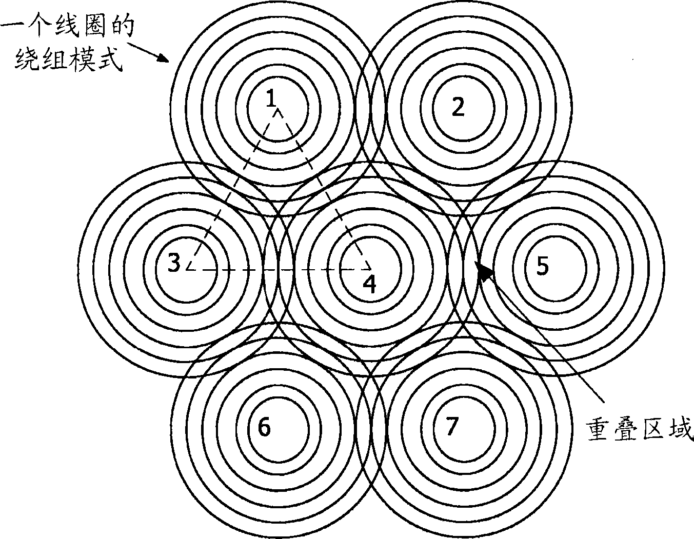
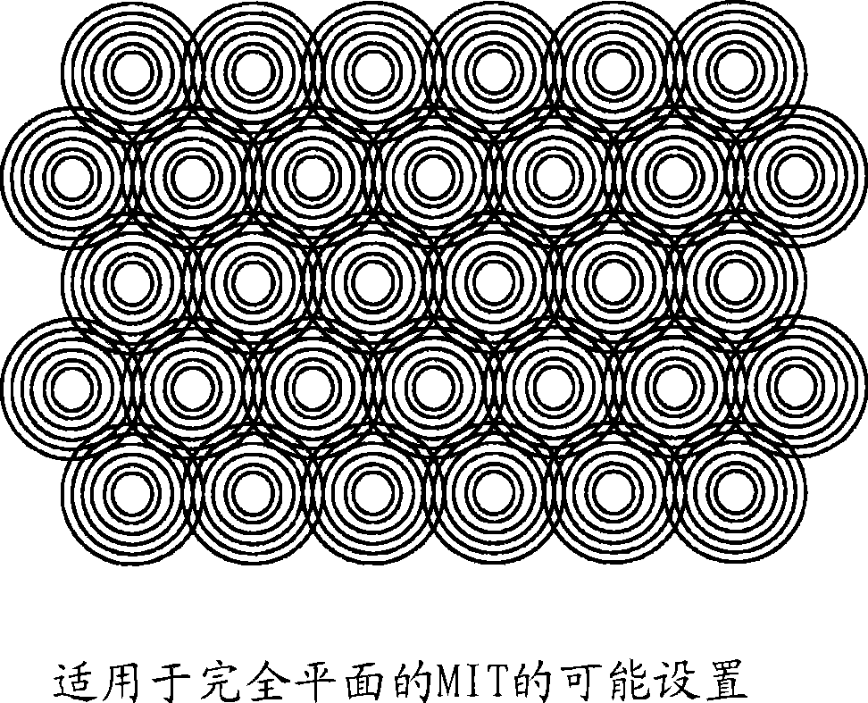
[0017] figure 1 A simplified structure containing 7 coils is shown. All coils are identical and can have several thin layers if necessary (eg for low frequency MIT). For simplicity, a coil with circular windings is shown in this figure and the alternation from outer to inner windings is omitted. The center points of the coils lie on an equilateral grid as shown by the dashed triangles, but they could of course be arranged in various other patterns (eg a square grid). The distance of the coils is determined by the requirement that no voltage is induced in a certain coil when adjacent coils are driven.

[0018] In other words, the distance is chosen such that adjacent coils are inductively decoupled from each other. for figure 1 For the setup in , coil 4 is inductively decoupled from all other coils, while eg coil 1 is decoupled from coils 2, 3, 4. In practice, the desired position is determined by measuring the induced voltage in one coil while applying a voltage to the ot...


PUM


Abstract

This invention relates to magnetic inductance tomography, and in particular, to coils of a sensor / driver cail array for use in a magnetic inductance tomography apparatus, in which driver / sensor coils are used to measure the induced flux in a conductive, dielectric and permittivity body, such as the human body. The sensor / driver coil array comprises at least one layer of thin coils whose centres are arranged on a regular grid, with adjacent coils overlapped by a suitable distance to cancel inductive neighbour coupling between them.

Description

technical field [0001] The present invention relates to magnetic induction tomography, and in particular to coils for magnetic induction tomography apparatus in which driver / sensor coils are used to measure induced flux in conductive, dielectric and permittivity bodies such as the human body . Background technique [0002] To study pathological conditions in the human body, various non-invasive techniques have been proposed previously, such as X-ray tomography, and electrical impedance tomography, in which the impedance distribution in a section of a living body is measured by attaching a series of electrodes, a small current through the series of electrodes. Other pairs of sensing electrodes are then used to make potential difference measurements, which provide data from which images can be constructed. [0003] A similar method of measuring impedance distribution that avoids direct attachment of sensors employs sets of driver / sense coils to induce magnetic flux in a cond...

Claims


Application Information

Patent Timeline
Patent Type & Authority Applications(China)
IPC IPC(8): G01R33/3415
CPCG01R33/3415G01R33/365A61B5/05G01R33/34007A61B5/0522
Inventor V·舒尔茨
Owner KONINKLIJKE PHILIPS ELECTRONICS NV
Why Eureka
Try Eureka